
One target holding a data wire LOW can stop every conversation on an I²C bus. A TCA4307 can separate the faulty branch and attempt recovery. That solves a transport problem; it does not establish that a target has returned the right bytes. Build two short segments, deliberately hold a downstream wire LOW, and compare the connection flag with a new reference read.
This is a design and host-software experiment. No physical waveform, assembled prototype or execution on the Pico is claimed. Use the exact connections and measurement conditions below; host checks are not an electrical qualification.
I²C means Inter-Integrated Circuit: a shared serial interface with a serial-data wire, SDA, and a serial-clock wire, SCL. Devices normally pull a wire LOW and release it for a resistor to pull HIGH. Open drain describes that pull-LOW-or-release behavior. A push-pull output that actively drives HIGH is not a suitable way to inject this fault.
U1, the TCA4307 integrated circuit (IC), sits between an upstream controller segment and a downstream target segment. U2 is an upstream reference memory at address 0x51; U3 is a downstream reference at 0x50. Both are the same exact memory type, so the experiment changes the fault boundary rather than the target protocol.
Ask separately: are the segments connected; did this transaction finish; and did this read return the expected reference bytes? READY answers only the first question. An acknowledgement, or ACK, is a device pulling the acknowledgement bit LOW; it does not certify the payload. A negative acknowledgement, or NACK, and a timeout both leave the requested result unavailable.
Use an original Raspberry Pi Pico with RP2040 and official RPI_PICO MicroPython 1.26.0. U1 is Texas Instruments TCA4307DGKR, the eight-pin DGK Very Thin Shrink Small-Outline Package (VSSOP), mounted on a continuity-checked passive 0.65 mm adapter. Do not assume an adapter label proves where pin 1 goes. U2 and U3 are Microchip 24LC256-I/P memories in eight-pin Plastic Dual In-Line Packages (PDIP). EEPROM expands to Electrically Erasable Programmable Read-Only Memory: it keeps its data when power is removed.
| Reference | Quantity and purpose |
|---|---|
| U1 | One TCA4307DGKR; buffers and disconnects the two bus segments. |
| U2, U3 | Two 24LC256-I/P; hold different 16-byte reference records. |
| R1–R4 | Four 2.2 kΩ ±1% resistors, Vishay MRS25000C2201FCT00; separate SDA/SCL pull-ups on each segment. |
| R5, R6 | Two 10 kΩ ±1% resistors, Vishay MRS25000C1002FCT00; READY pull-up and EN pull-down. |
| C1–C3 | Three 100 nF X7R ceramic capacitors rated at least 10 V; one local supply bypass per IC. |
| S1, S2 | Two normally open single-pole single-throw (SPST) momentary contacts; ground one downstream wire at a time. |
The unit symbols here are volts (V), kilohms (kΩ), nanofarads (nF), picofarads (pF), milliamperes (mA), milliwatts (mW), milliseconds (ms), microseconds (µs), nanoseconds (ns) and kilohertz (kHz). U1's operating supply is 2.3–5.5 V; its 7 V absolute maximum is a stress limit, not an operating choice. The 24LC256 operating range starts at 2.5 V. This entire fixture uses one nominal 3.3 V domain; no signal is pulled to 5 V.
Power the Pico only through its Universal Serial Bus (USB) connector. Its 3V3_OUT supplies this small fixture; all returns share ground. No second positive supply, long room cable or loose-jumper hot-plug is part of the experiment. Check the intended loaded rail and the manufacturer's 0.1–1000 ms supply-ramp recommendation. If the source, loading or ramp cannot be qualified, stop at the host-software exercise.
GPIO means general-purpose input/output. A Pico label such as GP0 is not the same number as the physical header position. The following package numbers are for the exact variants above, viewed according to their manufacturer drawings.
| Net | Connect these terminals |
|---|---|
| 3V3 | Pico 3V3_OUT, physical 36 → U1 VCC 8, U2 VCC 8, U3 VCC 8; the supply ends of R1–R5. |
| GND | Pico GND, physical 3 → U1 GND 4, U2 VSS 4, U3 VSS 4; R6's ground end and the ground ends of S1/S2. |
| SDAIN | Pico GP0, physical 1 ↔ U1 SDAIN 6 ↔ U2 SDA 5. R1 connects this net to 3V3. |
| SCLIN | Pico GP1, physical 2 ↔ U1 SCLIN 3 ↔ U2 SCL 6. R2 connects this net to 3V3. |
| SDAOUT | U1 SDAOUT 7 ↔ U3 SDA 5. R3 connects this net to 3V3; S1 connects it to GND only while pressed. |
| SCLOUT | U1 SCLOUT 2 ↔ U3 SCL 6. R4 connects this net to 3V3; S2 connects it to GND only while pressed. |
| READY | U1 READY 5 → Pico GP2, physical 4. R5 connects READY to 3V3. |
| EN | Pico GP3, physical 5 → U1 EN 1. R6 connects EN to GND, so the passive default is disabled. |
| U2 address | U2 A0 1 → 3V3; A1 2 and A2 3 → GND. Seven-bit address: 0x51. |
| U3 address | U3 A0 1, A1 2 and A2 3 → GND. Seven-bit address: 0x50. |
| Write protect | During observation, U2 WP 7 and U3 WP 7 → 3V3. Only during the separate setup operation, move each WP strap to GND with power OFF first. Never join both rails through a jumper. |
| Bypass | C1 across U1 VCC 8/GND 4; C2 across U2 VCC 8/VSS 4; C3 across U3 VCC 8/VSS 4, close to each package. |
Keep the two SDA nets distinct, and likewise the two SCL nets. Connecting them together around U1 defeats the isolation experiment. The Pico is the only clock controller. Do not let a second script reconfigure GP0/GP1 or actively drive the fault contacts. Use one shared ground for instruments on this common-domain fixture; it is not galvanic isolation.
One LOW pull-up branch: I = 3.3 V / 2200 Ω = 1.50 mA
Resistor power:          P = 3.3² / 2200 = 4.95 mW
READY pull-up current:   I = 3.3 V / 10000 Ω = 0.33 mA
EN pull-down load HIGH:  I = 3.3 V / 10000 Ω = 0.33 mA
RC example, 30%→70%:     tr = ln(0.7/0.3) × R × C
                            ≈ 0.8473 × 2200 Ω × 100 pF
                            ≈ 186 ns
RC means resistance-capacitance. The 100 pF is an illustrative total line capacitance, not a measurement of a breadboard. The memory's table specifies a maximum 300 ns rise at this supply range. Do not substitute a generic slower-bus allowance merely because the program requests 100 kHz. Qualify both segments with a suitable oscilloscope, including loaded LOW voltages and the buffer's active rise-time accelerators. The offset specified under a 10 kΩ test condition is not an automatic guarantee for our 2.2 kΩ network.
Four simultaneously LOW pull-up branches would draw a nominal total 6 mA from the rail; that is not a claim that all of it flows through one IC pin. Active accelerators add transient current. The calculations neither establish a complete supply-current budget nor qualify the board's regulator or waveform. Reject extra unknown breakout pull-ups rather than silently changing the parallel resistance.
TI's SCPS270B lists a 25/40/65 ms minimum/typical/maximum stuck timer and a 5.5/8.5/14 kHz recovery-clock range. The device can disconnect the segments and attempt up to 16 downstream clock pulses, then a STOP and reconnection qualification. A contact physically holding SCLOUT LOW cannot be forced HIGH by those attempts. Reconnection also needs the required idle/STOP and released output-side conditions. Thus “40 ms” is not a universal success deadline.
READY is an open-drain connection indicator. HIGH permits a new attempt to read U3; LOW makes the downstream result unavailable. Neither state certifies a memory, a sensor, calibration or the contents of a previous transaction. Our fields upstream_reference_match and downstream_reference_match mean only that the corresponding read returned its specified bytes. Another device with the same address and bytes could pass it.
Save the complete file below as tca4307-recovery-requalification.py on the Pico. Do not name it main.py; this lesson does not need automatic boot execution. The Read-Evaluate-Print Loop (REPL) is MicroPython's interactive command prompt. Load the functions without running the observation:
ns = {"__name__": "tca91"}
exec(open("tca4307-recovery-requalification.py").read(), ns)ns["pico_session"](provision=True, allow_write=True). This writes the two different 16-byte records at byte address 0x0100 and reads them back. Each record fits inside one 64-byte page.ns["main"]() once. This default path performs no EEPROM data writes. It makes a finite observation session and attempts to disable U1 on exit.The two payloads are fixture references, not secret identifiers. This program is not an EEPROM endurance test or a general settings store. The two-record EEPROM lesson covers interrupted settings updates separately.
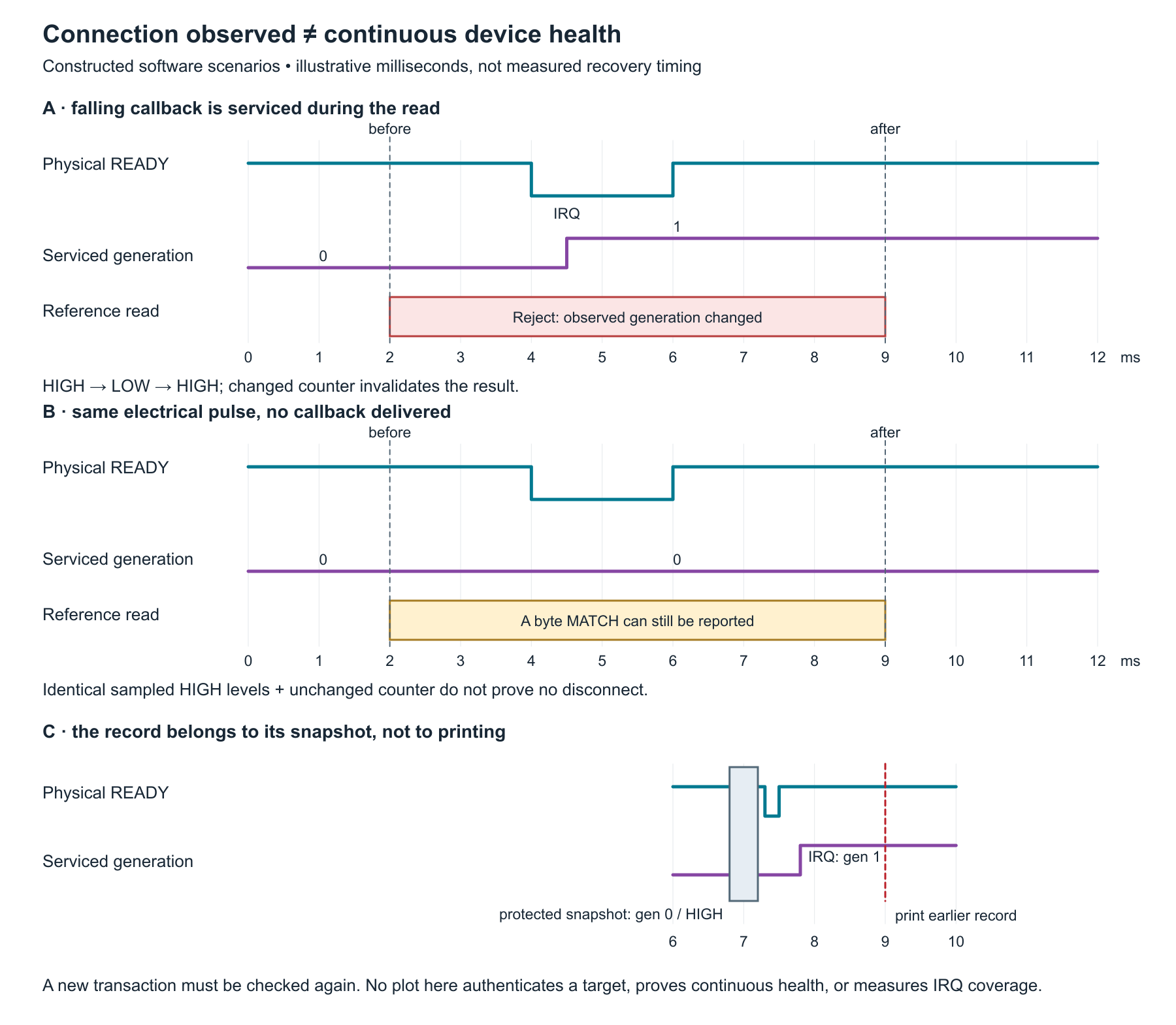
A before/after poll can read HIGH twice even if READY briefly fell in the middle. The code therefore uses a hard interrupt request (IRQ) callback on a falling edge. The selected RP2 port supports hard=True. The callback increments a small, saturating generation counter; it does no I²C, printing or scheduling. Its overflow and exception flags are sticky. The main program never clears the generation during a session.
A snapshot briefly masks interrupts, copies the generation/fault flags and reads the level, then restores interrupt state. A read is accepted only when its before/after marks agree. At the end of the step, changed marks remove older results from that step. An upstream read can still match while a stable downstream disconnect is observed; downstream reads require READY HIGH.
This mechanism records serviced falling events, not every electrical pulse. The hardware can coalesce events; an edge can occur while interrupts are masked or the interpreter is unavailable. A pending callback can run after a snapshot's interrupt mask is restored. The returned record belongs to its final protected snapshot; it does not prove the connection remains valid until printing, after printing, or between all software observations. This code deliberately has no alarm, valve or safety action.
The host suite demonstrates both cases on the actual program: an injected falling callback during a read invalidates it even though both sampled levels are HIGH; an equally brief pulse with no delivered callback is not detectable from those levels. That counterexample is a stated measurement limit, not silently relabelled continuous coverage.
Download the same full Python file. The application programming interface (API) is pinned to the selected MicroPython version. Its RP2 I²C constructor enables weak pull-ups; the subsequent init(pull=None) calls clear the pulls while preserving the I²C alternate function. Do not replace those calls with a change to input/output mode.
The configured 20000 µs timeout is supported by this port and applies to each low-level transfer; it is not an exact 20 ms deadline for the complete random-read operation. The session also checks a software elapsed-time budget and a finite step limit. Its clock guard rejects a backward or excessive observed service gap. The modular tick difference is unambiguous only when the true interval is less than half the tick counter’s period. A wholly unobserved wrap can alias the same raw value, which this code cannot diagnose; the one-second service-gap assumption must hold. The step cap still ends a loop whose clock stops advancing. None of these host checks measures real execution time.
"""TCA4307 reference-read experiment, original RP2040 Pico / MicroPython 1.26.0.

Only observed READY events are tracked. This is not a lossless event recorder,
sensor-health monitor, or authenticated silicon-identity check. No hardware run
or target build is claimed. Ordinary observation never writes EEPROM data.
"""

UPSTREAM = 0x51
DOWNSTREAM = 0x50
OFFSET = 0x0100
UP_BYTES = b"TC91_UP_REF_v001"
DOWN_BYTES = b"TC91_DN_REF_v001"
MAX_FALLS = 65535


class ObservationFault(RuntimeError):
    pass


def positive_int(value, name, maximum):
    if type(value) is not int or not 1 <= value <= maximum:
        raise ValueError(name)
    return value


class ReadyCapture:
    """Saturating observed-edge generation; hard IRQ body does no I2C/printing."""

    def __init__(self, level, disable_irq, enable_irq):
        self.level = level
        self.disable_irq = disable_irq
        self.enable_irq = enable_irq
        self.falls = 0
        self.overflow = False
        self.callback_fault = False

    def falling(self, unused_pin):
        try:
            if self.falls < MAX_FALLS:
                self.falls += 1
            else:
                self.overflow = True
        except BaseException:
            self.callback_fault = True

    def snapshot(self):
        token = self.disable_irq()
        try:
            mark = (self.falls, self.overflow, self.callback_fault, self.level())
        finally:
            self.enable_irq(token)
        if mark[1] or mark[2]:
            raise ObservationFault("READY_CAPTURE_FAULT")
        if type(mark[3]) is not int or mark[3] not in (0, 1):
            raise ObservationFault("READY_LEVEL_FAULT")
        return mark


class ElapsedClock:
    """Unwrap ticks only while each service gap is within the stated bound."""

    def __init__(self, raw_ticks, ticks_diff, max_gap_ms=1000):
        self.raw_ticks = raw_ticks
        self.ticks_diff = ticks_diff
        self.max_gap_ms = positive_int(max_gap_ms, "max_gap_ms", 10000)
        self.previous = raw_ticks()
        if type(self.previous) is not int:
            raise ObservationFault("CLOCK_TYPE")
        self.elapsed = 0
        self.failed = False

    def now(self):
        if self.failed:
            raise ObservationFault("CLOCK_FAULT")
        try:
            raw = self.raw_ticks()
            if type(raw) is not int:
                raise ObservationFault("CLOCK_TYPE")
            delta = self.ticks_diff(raw, self.previous)
            if type(delta) is not int or not 0 <= delta <= self.max_gap_ms:
                raise ObservationFault("CLOCK_GAP")
            self.previous = raw
            self.elapsed += delta
            return self.elapsed
        except BaseException:
            self.failed = True
            raise


class ReferenceObserver:
    def __init__(self, bus, capture):
        self.bus = bus
        self.capture = capture
        self.observation = 0

    def _reference(self, address, expected, require_connected):
        before = self.capture.snapshot()
        if require_connected and before[3] == 0:
            return None, "DISCONNECTED", before
        try:
            data = self.bus.readfrom_mem(address, OFFSET, len(expected), addrsize=16)
        except OSError:
            after = self.capture.snapshot()
            return None, "I2C_ERROR", after
        after = self.capture.snapshot()
        if before != after:
            return None, "OBSERVED_READY_CHANGE", after
        if require_connected and after[3] == 0:
            return None, "DISCONNECTED", after
        if type(data) is not bytes or len(data) != len(expected):
            return None, "INVALID_READ", after
        return data == expected, "MATCH" if data == expected else "MISMATCH", after

    def step(self):
        # Every step makes new reads. No prior successful payload is reused.
        up, up_reason, up_mark = self._reference(UPSTREAM, UP_BYTES, False)
        down, down_reason, down_mark = self._reference(DOWNSTREAM, DOWN_BYTES, True)
        end = self.capture.snapshot()
        if up_mark != end:
            up, up_reason = None, "OBSERVED_READY_CHANGE"
        if down_mark != end or end[3] == 0:
            down, down_reason = None, "OBSERVED_READY_CHANGE" if down_mark != end else "DISCONNECTED"
        self.observation += 1
        return {
            "observation": self.observation,
            "ready_level_at_end": end[3],
            "observed_falls": end[0],
            "upstream_reference_match": up,
            "upstream_reason": up_reason,
            "downstream_reference_match": down,
            "downstream_reason": down_reason,
            "scope": "THIS_REFERENCE_READ_ONLY",
        }


def supervise(observer, capture, en_write, now_ms, sleep_ms, emit,
              duration_ms=10000, step_limit=220, interval_ms=50):
    """Finite session. OFF is attempted even for bad arguments or output errors.

    A returned summary is CLOSED, never a continuing verification of a device.
    A cleanup failure raises; it cannot produce a successful return.
    """
    try:
        en_write(0)
        positive_int(duration_ms, "duration_ms", 60000)
        positive_int(step_limit, "step_limit", 2000)
        positive_int(interval_ms, "interval_ms", 1000)
        start = now_ms()
        if type(start) is not int or start < 0:
            raise ObservationFault("CLOCK_TYPE")
        previous = start
        en_write(1)
        emit({"session": "START", "scope": "OBSERVED_REFERENCE_READS"})
        completed = 0
        reason = "STEP_LIMIT"
        for unused in range(step_limit):
            before = now_ms()
            if type(before) is not int or before < previous:
                raise ObservationFault("CLOCK_ORDER")
            previous = before
            if before - start >= duration_ms:
                reason = "TIME_LIMIT"
                break
            record = observer.step()
            after = now_ms()
            if type(after) is not int or after < previous:
                raise ObservationFault("CLOCK_ORDER")
            previous = after
            if after - start >= duration_ms:
                reason = "TIME_LIMIT_DURING_READ"
                break  # Never label an over-budget transaction as a timely one.
            record["observer_elapsed_ms"] = after - start
            emit(record)
            completed += 1
            sleep_ms(interval_ms)
        # Include callbacks that happened in the final emit/sleep. This is a
        # diagnostic count, not a claim that every electrical pulse was caught.
        end = capture.snapshot()
        summary = {"session": "CLOSED", "observations": completed,
                   "reason": reason, "observed_falls_before_disable": end[0],
                   "current_device_verification": None}
    finally:
        en_write(0)
    return summary


def provision_references(bus, capture, delay_ms, allow_write=False):
    """Explicit setup helper; WP must be LOW and EN/READY already qualified.

    Each16-byte record fits one64-byte page. This is not called by main().
    Power OFF before moving the physical WP straps back HIGH.
    """
    if allow_write is not True:
        raise ValueError("explicit allow_write=True required")
    for address, payload in ((UPSTREAM, UP_BYTES), (DOWNSTREAM, DOWN_BYTES)):
        before = capture.snapshot()
        if before[3] != 1:
            raise ObservationFault("SETUP_NOT_CONNECTED")
        bus.writeto_mem(address, OFFSET, payload, addrsize=16)
        delay_ms(10)  # Datasheet write-cycle maximum5ms; wait is not an ACK test.
        check = bus.readfrom_mem(address, OFFSET, len(payload), addrsize=16)
        if before != capture.snapshot() or check != payload:
            raise ObservationFault("SETUP_VERIFY_FAILED")


def pico_session(provision=False, allow_write=False):
    import machine
    import micropython
    import time
    import json
    en = None
    ready = None
    try:
        en = machine.Pin(3, machine.Pin.OUT, value=0)
        ready = machine.Pin(2, machine.Pin.IN)
        micropython.alloc_emergency_exception_buf(128)
        capture = ReadyCapture(ready.value, machine.disable_irq, machine.enable_irq)
        ready.irq(handler=capture.falling, trigger=machine.Pin.IRQ_FALLING, hard=True)
        sda, scl = machine.Pin(0), machine.Pin(1)
        bus = machine.I2C(0, sda=sda, scl=scl, freq=100000, timeout=20000)
        # rp2 I2C construction enables weak pulls. Clear only pulls, preserving
        # the I2C alternate function; external R1-R4 are the specified pulls.
        sda.init(pull=None)
        scl.init(pull=None)
        clock = ElapsedClock(time.ticks_ms, time.ticks_diff)
        if provision:
            if allow_write is not True:
                raise ValueError("explicit allow_write=True required")
            en.value(1)
            time.sleep_ms(20)
            provision_references(bus, capture, time.sleep_ms, allow_write=True)
            return {"setup": "REFERENCE_BYTES_WRITTEN_AND_READ_BACK"}
        observer = ReferenceObserver(bus, capture)
        return supervise(observer, capture, en.value, clock.now, time.sleep_ms,
                         lambda record: print(json.dumps(record)))
    finally:
        # Detach still runs if OFF raises. No success is returned on either
        # cleanup failure. R6 remains a passive default, not a fault guarantee.
        try:
            if en is not None:
                en.value(0)
        finally:
            if ready is not None:
                ready.irq(handler=None)


def main():
    result = pico_session()
    print(result)


if __name__ == "__main__":
    main()
null in the normal console records. No missing read becomes numeric zero.The final summary says CLOSED and has no current device verification. Prior console records are historical observations. A fault during console output cannot turn a returned closed summary into an ongoing health certificate. Record the physical release/press timing separately; observer elapsed time is a receiver-side clock, not a target measurement timestamp.
The provided host test file executes the delivered functions with injected bus, IRQ and clock adapters. 20 unittest groups pass in the recorded host run. They cover fresh reads after errors, address/payload mismatch, observed and unobserved short pulses, capture saturation, clock/order faults, finite exits, provisioning gates and exception cleanup. They do not execute RP2040 firmware, test an analog edge, or establish physical recovery. The blank worksheet is for real readings; no sample data are supplied as measurements.
This lesson extends the unbuffered I²C detective experiment; it does not replace that diagnosis with a universal bus-repair promise. The electronics course provides the supporting circuit fundamentals.
A log shows READY HIGH before and after a read, the expected 16 bytes, and the same observed-fall generation. Can you conclude there was no disconnect during the read? What extra fact does a generation change provide?
No. Those observations support only the qualified reference read and the events the implementation actually captured. A pulse with no serviced callback can leave both levels and the counter unchanged. A generation change positively records at least one observed falling event, so this implementation rejects an in-flight result spanning it. It still does not measure every pulse, authenticate the memory, or certify future operation.