Pico · Producer and consumer experiment
Pico PIO Capture: A Full FIFO Changes the Experiment
A clean sequence of capture tokens can conceal a long blind interval. Deliberately delay the reader of a Pico's hardware queue, then compare a producer that stalls with one that discards words. Learn what the queue and its sticky flag actually establish before turning a token list into an event history.
1. Name the moving parts first
The original Raspberry Pi Pico contains the RP2040 microcontroller. Its programmable input/output (PIO) hardware executes small programs independently of the main processor. A state machine (SM) is one such instruction executor. This lesson reserves state machine 0 in PIO block 0, written PIO0/SM0. Its receive (RX) first-in, first-out (FIFO) queue holds four 32-bit words in their arrival order. Each word is a bundle of 32 binary digits. The separate transmit (TX) queue is unused; the two queues are not joined.
The input shift register (ISR) is a different 32-bit holding register inside the state machine. A PUSH instruction attempts to copy its word into the RX FIFO. A full queue creates backpressure: the consumer has not removed enough data for the producer to continue as designed. A sticky flag remembers that a condition occurred until software explicitly clears it. The RXSTALL flag records a full-queue PUSH condition in this experiment, whether the chosen instruction stalls or drops a word.
The input comes from pulse-width modulation (PWM), a hardware waveform with alternating HIGH and LOW intervals. General-purpose input/output (GPIO) pin GP16 is the sole output owner. GP17 is an input. Universal Serial Bus (USB) supplies the Pico and carries its console connection. No external generator, second board or powered sensor connects to the signal node.
The selected firmware is official RPI_PICO MicroPython 1.26.0 on an original RP2040 Pico, not Pico W or Pico 2. The program checks the reported 125 megahertz (MHz) system clock without changing it. Host tests assembled the actual PIO function with the pinned MicroPython assembler and executed those opcodes in rp2040-pio-emulator 0.88.0. Those are host encoding and emulation results, not a Pico firmware build, target execution, measured waveform or physical bench result.
2. One output, one input and a resistor
Use a short breadboard connection and a 1 kilohm (kΩ), ±1% resistor. Volt (V), milliampere (mA), microampere (µA), millisecond (ms) and microsecond (µs) denote voltage, current and time units below. A header's physical pin number is distinct from its GP number. Ground (GND) is the common electrical reference. Hertz (Hz) means cycles per second; one kilohertz (kHz) is 1000 Hz.

| Terminal | Connection | Purpose |
|---|---|---|
| Pico GP16, physical 21 | R1 → GP17, physical 22 | 1000 Hz requested PWM, nominal 50% duty. |
| Pico GP17, physical 22 | R1 only; internal pull-down enabled | PIO's input base; remains an input throughout. |
| Pico GND, physical 23 | Existing board common ground | Reference for a same-domain oscilloscope probe. No extra board-to-board ground wire is needed. |
| Micro-USB connector | Host USB cable only | Board power and console. Leave the system-supply input (VSYS) and regulated 3.3 V output (3V3) headers unused. |
| R1 | 1 kΩ ±1%, for example Vishay MRS25000C1001FCT00 | Series current limiting, not level shifting or overvoltage protection. |
At an assumed 3.3 V, an accidental short after the minimum 990 Ω resistor gives 3.3/990 ≈ 3.33 mA. That calculation does not establish an absolute fault-current ceiling for an unspecified rail. The normal input load is far smaller. The datasheet gives a 50–80 kΩ internal pull-down; using 50 kΩ gives at most about 66 µA at an assumed 3.3 V before considering the series resistor. The illustrative voltage drop across 1 kΩ is about 66 mV. The pin's specified maximum input leakage of 1 µA adds another illustrative 1 mV error contribution.
At a 3.3 V input/output supply, the digital table specifies a minimum HIGH input of 2.0 V and maximum LOW input of 0.8 V. Its output HIGH minimum is 2.62 V and output LOW maximum 0.5 V under the stated drive-load conditions. These values support this lightly loaded same-domain connection; they are not measured levels from a prototype. Check actual HIGH/LOW and pulse shape with a suitable high-impedance oscilloscope before relying on a physical capture. A drive-strength setting is not a hard current limiter. Keep the input within the operating rail limits; the resistor does not make it a 5 V input.
Power off before moving the resistor. Leave GP17's input direction and pull configuration under this program's control. Do not attach another generator to GP16 or GP17. All other header pins are unused. This simple fixture intentionally avoids translating or qualifying an external signal.
3. The same event token, two PUSH instructions
The PIO routine initializes scratch register X to all ones before entering its loop. It waits for LOW, waits for HIGH, copies X into the ISR, pushes it and decrements X. The Python reader decodes an index as word ^ 0xffffffff, so the first token is zero. There is no sampling of an input counter value into the word, and no timestamp is encoded. A token means that this program completed a qualified LOW-to-HIGH wait sequence.
With push(block), a full FIFO leaves the pending word in the ISR and the state machine waits at PUSH. Four words are queued; a fifth word may be pending outside that queue. While stalled, the program does not execute later WAIT instructions. Complete input pulses can pass unnoticed. After space becomes available, the pending word can enter the FIFO and the local sequence resumes. Its indices can remain perfectly contiguous despite the blind interval.
With push(noblock), a full FIFO leaves its four queued words unchanged, discards the attempted word, clears the ISR and continues. X still decrements, so an interior gap in later exported indices can reveal missing PUSH attempts. It does not count every missed physical pulse: the WAIT program and input synchronizer still have acceptance limits. The input synchronizer uses two hardware sampling stages to reduce the risk from a signal changing near a system-clock edge; it does not make every arbitrarily short pulse observable. If all discarded attempts are at the end, the exported list might be only 0,1,2,3, with no interior gap at all.
Both cases set the same RXSTALL bit. It is not a lost-word count, and the name does not prove that the selected instruction blocked. The code writes only bit zero at PIO0's FDEBUG address 0x50200008 to clear its own SM0 flag before the trial. This write-one-to-clear operation writes a one to the selected bit; a read-modify-write could accidentally clear other state machines' flags. No other program may use SM0, its FIFO or that flag during the experiment.
Exact host-assembled words, hexadecimal; wrap bottom 1, top 5:
block:   a02b 2020 20a0 a0c1 8020 0041
noblock: a02b 2020 20a0 a0c1 8000 0041

Only the PUSH Block bit differs: 0x8020 versus 0x8000.
4. Read the constructed comparison carefully
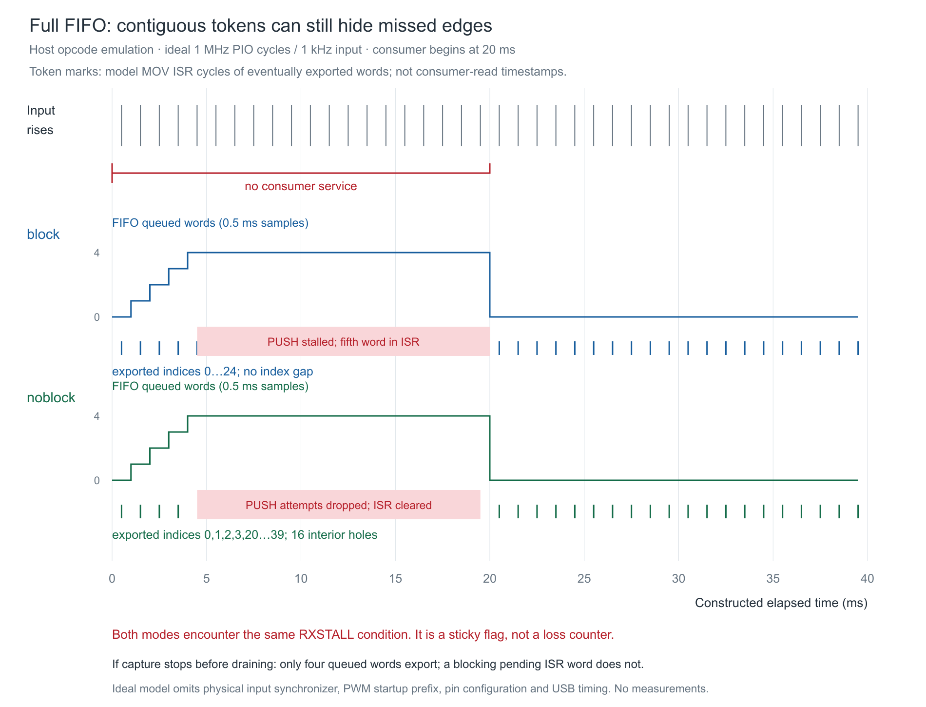
The ideal model uses a 1 MHz PIO clock, a 1 kHz input with its first rising transition at 0.5 ms, and a consumer that starts at 20 ms. Before that service, the first four tokens fit. Blocking PUSH holds index 4, then the next captured index 5 is associated with the model's 20.501 ms observation cycle rather than 5.501 ms. The final export contains 25 contiguous indices, 0–24. Nonblocking mode exports 24 indices: 0–3 and 20–39. Its sixteen interior holes correspond to discarded attempts in this particular ideal schedule.
The figure models forty milliseconds to keep the comparison readable; the board program requests an eighty-millisecond serviced trial. At 1 kHz, four queue slots fill in roughly four milliseconds if nothing drains them. That is a budget estimate, not a promise that Python wakes at a particular edge. The first input HIGH may be partial when the state machine starts, and WAIT LOW deliberately does not count that partial HIGH as a new event.
The RP2040 normally synchronizes PIO inputs through two system-clock stages. The instruction sequence and divider add their own delays. The host emulator does not reproduce physical synchronization, pin multiplexing, PWM startup phase, USB activity or analog edge quality. It also does not emulate the FDEBUG register; the test harness identifies a full-PUSH condition and applies the datasheet's flag rule. Keep that distinction when comparing its output with a future real register read.
5. Run one finite trial at a time
Save the complete file below as pico_pio_backpressure.py on the Pico using your normal editor. Start from a clean, cold-powered MicroPython session with no background code, direct memory access (DMA) transfer, interrupt request (IRQ) handler or second FIFO reader using SM0. Leave input synchronization at its reset default; this program does not set a bypass. The MicroPython Application Programming Interface (API) exposes a FIFO read that blocks on empty, so a second consumer would break the level-then-read assumption.
Use the read-evaluate-print loop (REPL) and execute this block once. It loads the file without auto-starting it, then explicitly starts one trial. Do not save it as main.py or add automatic repetition.
scope = {}
exec(open("pico_pio_backpressure.py").read(), scope)
scope["main"](blocking=True, hold_ms=20)
After it returns, call scope["main"](blocking=False, hold_ms=20) for the comparison. Run each mode with hold_ms=0 as a control. The control is not guaranteed to be lossless: Python scheduling and startup can still create backpressure. Record the flag and the actual output rather than replacing them with the ideal model's numbers.
The deliberate hold is checked against its requested duration with a 2 ms returned-overrun allowance; the serviced trial plus stopping is checked with a 5 ms allowance. These are acceptance policies for returned calls. A stalled interpreter or hardware call cannot be interrupted by those checks. The code requests only 40–100 ms serviced trials, bounds its software loops and exports no more than 256 tokens.
observed_start_after_us is the span from the first clock observation, before initialization, to the observation after start() returns. That startup prefix can already contain source edges. It is not a measured activation time, and the subsequent requested 80 ms is not the total physical PWM-active interval. The model assumes an ideal zero startup prefix. Actual initialization latency, the first partial pulse and phase are additional reasons not to derive an expected physical edge count from requested duration.
The clock rejects a returned negative difference or an observed service gap above 100 ms. MicroPython's tick counter wraps; an entirely unobserved full tick turn can alias to the same value. This short-run, frequently serviced assumption is necessary, and neither that guard nor a finite loop supplies a physical hard cutoff.
6. Complete capture program
The hardware adapter keeps the SM0 handle before initialization, so a later initialization error still permits an independent stop attempt. It explicitly establishes an empty FIFO and initializes X in the actual program; restart() alone is not used as a FIFO-flush promise. The file caches its two program objects so repeated calls reuse their loaded offsets instead of allocating another six instructions each time. Load the file once per cold-powered session as shown; repeatedly executing the whole file would create another cache and can consume instruction memory. Normal closure first stops the PWM source and PIO producer, then drains only queued words and reads the sticky flag. A pending ISR word is not silently exported by that final FIFO drain.
"""Original RP2040 Pico / MicroPython 1.26.0; bounded PIO FIFO experiment.
Owns PIO0 SM0, PWM on GP16, input GP17. No other FIFO reader, IRQ or DMA.
Host tests/emulation are not execution on a Pico.
"""
MASK = 0xffffffff
FDEBUG = 0x50200008
RXSTALL_SM0 = 1
SOURCE_HZ = 1000
PIO_HZ = 1000000
_PROGRAM_MODULE = None
_PROGRAM_CACHE = {}


def make_program(rp2, blocking):
    global _PROGRAM_MODULE, _PROGRAM_CACHE
    if type(blocking) is not bool:
        raise ValueError('BLOCKING')
    if _PROGRAM_MODULE is not rp2:
        _PROGRAM_MODULE, _PROGRAM_CACHE = rp2, {}
    if blocking in _PROGRAM_CACHE:
        return _PROGRAM_CACHE[blocking]
    @rp2.asm_pio(fifo_join=rp2.PIO.JOIN_NONE)
    def capture_edges():
        mov(x, invert(null))
        wrap_target()
        label('edge')
        wait(0, pin, 0)
        wait(1, pin, 0)
        mov(isr, x)
        if blocking:
            push(block)
        else:
            push(noblock)
        jmp(x_dec, 'edge')
        wrap()
    _PROGRAM_CACHE[blocking] = capture_edges
    return capture_edges


class Clock:
    def __init__(self, ticks, diff):
        self.ticks, self.diff = ticks, diff
        self.previous = ticks()
        self.elapsed = 0

    def read(self):
        raw = self.ticks()
        delta = self.diff(raw, self.previous)
        if type(delta) is not int or not 0 <= delta <= 100000:
            raise RuntimeError('CLOCK_OR_SERVICE_GAP')
        self.previous = raw
        self.elapsed += delta
        return self.elapsed


class Hardware:
    def __init__(self, machine=None, rp2=None):
        # No I/O until start(); every returned resource is inside capture's finally.
        self.machine, self.rp2 = machine, rp2
        self.output = self.input = self.pwm = self.sm = None

    def start(self, blocking):
        if self.machine is None:
            import machine
            import rp2
            self.machine, self.rp2 = machine, rp2
        m = self.machine
        if m.freq() != 125000000:
            raise RuntimeError('REQUIRE_125_MHZ_SYSTEM_CLOCK')
        self.output = m.Pin(16, m.Pin.OUT, pull=None, value=0)
        self.input = m.Pin(17, m.Pin.IN, m.Pin.PULL_DOWN)
        self.pwm = m.PWM(self.output, freq=SOURCE_HZ, duty_u16=0)
        self.sm = self.rp2.StateMachine(0)
        self.sm.active(0)
        self.sm.init(make_program(self.rp2, blocking),
                     freq=PIO_HZ, in_base=self.input)
        # Do not rely on restart() to flush the FIFO. Exclusive SM0 ownership.
        for _ in range(4):
            if self.sm.rx_fifo() == 0:
                break
            self.sm.get()
        if self.sm.rx_fifo() != 0:
            raise RuntimeError('FIFO_NOT_EMPTY')
        m.mem32[FDEBUG] = RXSTALL_SM0  # Write-one-to-clear only our sticky bit.
        self.sm.active(1)
        self.pwm.duty_u16(32768)

    def level(self):
        n = self.sm.rx_fifo()
        if type(n) is not int or not 0 <= n <= 4:
            raise RuntimeError('FIFO_LEVEL')
        return n

    def get(self):
        return self.sm.get()  # Caller has checked level; exactly one consumer.

    def flag(self):
        return bool(self.machine.mem32[FDEBUG] & RXSTALL_SM0)

    def stop(self):
        """Independent best-effort attempts; any failure prevents successful return."""
        errors = []
        if self.pwm is not None:
            try:
                self.pwm.duty_u16(0)
            except BaseException as exc:
                errors.append(exc)
        if self.sm is not None:
            try:
                self.sm.active(0)
            except BaseException as exc:
                errors.append(exc)
        if self.pwm is not None:
            try:
                self.pwm.deinit()
                self.pwm = None
            except BaseException as exc:
                errors.append(exc)
        if self.machine is not None:
            try:
                if self.output is None:
                    self.output = self.machine.Pin(16, self.machine.Pin.OUT, pull=None, value=0)
                else:
                    self.output.init(self.machine.Pin.OUT, pull=None, value=0)
            except BaseException as exc:
                errors.append(exc)
        if errors:
            raise errors[0]


def drain(io, words):
    # At most four queued words per call. Producer can run during normal service.
    for _ in range(4):
        if io.level() == 0:
            break
        word = io.get()
        if type(word) is not int or not 0 <= word <= MASK:
            raise RuntimeError('WORD')
        words.append(word)
        if len(words) > 256:
            raise RuntimeError('RECORD_LIMIT')


def summarize(words, blocking, flag, hold_ms, start_after_us, stopped_after_us):
    indices = [w ^ MASK for w in words]
    if not indices or indices[0] != 0:
        raise RuntimeError('NO_INITIAL_TOKEN')
    gaps = 0
    for a, b in zip(indices, indices[1:]):
        if not a < b <= 100000:
            raise RuntimeError('TOKEN_ORDER')
        gaps += b-a-1
    if gaps and not flag:
        raise RuntimeError('GAP_WITHOUT_OBSERVED_FLAG')
    return dict(mode='block' if blocking else 'noblock',
                result='BACKPRESSURE_OBSERVED' if flag else 'NO_BACKPRESSURE_OBSERVED',
                rxstall=bool(flag), exported_tokens=len(words), token_indices=indices,
                interior_missing_indices=gaps, consumer_hold_ms=hold_ms,
                observed_start_after_us=start_after_us, stopped_after_us=stopped_after_us,
                complete_event_history=False,
                physical_edges_during_blind_intervals=None,
                token_times=None)


def capture(blocking=True, hold_ms=20, total_ms=80, *, io=None,
            ticks=None, diff=None, sleep_us=None):
    if type(blocking) is not bool or type(hold_ms) is not int or not 0 <= hold_ms <= 30:
        raise ValueError('MODE/HOLD')
    if type(total_ms) is not int or not 40 <= total_ms <= 100 or hold_ms >= total_ms:
        raise ValueError('DURATION')
    if ticks is None:
        import time
        ticks, diff, sleep_us = time.ticks_us, time.ticks_diff, time.sleep_us
    if io is None:
        io = Hardware()
    words = []
    try:
        clock = Clock(ticks, diff)
        io.start(blocking)
        started = clock.read()  # Includes observed start/constructor latency.
        for _ in range(1000):
            if clock.read()-started >= hold_ms*1000:
                break
            sleep_us(100)
        else:
            raise RuntimeError('HOLD_BUDGET')
        hold_ended = clock.read()
        if hold_ended-started > hold_ms*1000+2000:
            raise RuntimeError('HOLD_OVERRUN')
        for _ in range(2000):
            if clock.read()-started >= total_ms*1000:
                break
            drain(io, words)
            sleep_us(100)
        else:
            raise RuntimeError('SERVICE_BUDGET')
        io.stop()  # Stop both source and producer BEFORE final FIFO drain/flag.
        stopped = clock.read()
        if stopped-started > total_ms*1000+5000:
            raise RuntimeError('DURATION_OVERRUN')
        drain(io, words)
        if io.level() != 0:
            raise RuntimeError('FINAL_FIFO')
        flag = io.flag()
        result = summarize(words, blocking, flag, hold_ms, started, stopped)
        result['observed_consumer_hold_us'] = hold_ended-started
        return result
    finally:
        io.stop()  # Also covers startup, console-independent and BaseException paths.


def main(blocking=True, hold_ms=20):
    import json
    result = capture(blocking, hold_ms)
    print(json.dumps(result))  # No sample output until capture and cleanup return.
    return result
The final cleanup independently requests zero duty, disables the state machine, deinitializes PWM and remaps the owned GP16 pin to a LOW output. Deinitializing PWM alone is not a physical LOW guarantee. Any cleanup exception prevents a successful return, and printing occurs only after capture and cleanup return. If console output fails afterward, hardware cleanup has already been attempted; that exception still does not establish a current physical pin level. The program is a short experiment, not a supervised safety function.
BACKPRESSURE_OBSERVED taints the whole trial even when the exported indices are contiguous. NO_BACKPRESSURE_OBSERVED means only that the selected sticky condition was not observed in this run. Both results explicitly carry complete_event_history=false, unknown physical edges during blind intervals and no token timestamps. An empty initial capture, malformed word, inconsistent order or an interior gap without the expected flag raises instead of inventing successful data.
7. Bench procedure and fault checks
- With power off, identify the original Pico and physical pins 21, 22 and 23 from its pinout. Fit R1 between 21 and 22. Inspect for adjacent-pin shorts. Connect only the USB cable.
- Verify MicroPython 1.26.0, the selected board and reported
machine.freq()of 125000000. The program rejects another reported system frequency instead of changing clocks or overclocking the board. - Using a suitable high-impedance oscilloscope referred to pin 23, inspect GP16 and GP17 during a finite run. Check signal amplitude, period and direction ownership. Host emulation supplies none of these measurements.
- Run each mode with no deliberate hold, then a 20 ms hold. Copy the complete returned record into a separate log. Record startup prefix, serviced stop bracket, queued token count, missing interior indices and RXSTALL independently.
- Repeat without moving the link. A different startup phase or scheduling pause can change the counts. Compare the kind of failure, not equality to the figure's ideal counts.
- Power off, remove R1, then power up and run once. The input pull-down may leave no observed rising sequence, so
NO_INITIAL_TOKENis expected. It does not prove which physical wiring fault occurred. Restore the link with power off. - Run the host tests from the downloaded archive. They test the actual capture controller with faults, the pinned assembler and opcode-emulator PUSH semantics, including a case that stops with only four queued words and a pending fifth ISR word. They do not certify real pulse acceptance.
The blank worksheet has no sample rows. Keep future oscilloscope observations separate from emulator cycles. Never assign evenly spaced timestamps to exported words after a stall or dropout. That would turn missing evidence into a smooth but false waveform.
The complete experiment and host-test archive contains the program, blank worksheet, editable diagrams, exact assembler source and instructions. In an isolated Python virtual environment install rp2040-pio-emulator==0.88.0, then run python test_capture.py. This validates host behavior only. No Pico target firmware build or execution was performed. The older software frequency-counting and quiet analog-capture lessons do not establish this PIO queue behavior.
8. Challenge: four contiguous words and a flag
A nonblocking trial returns 0,1,2,3 with RXSTALL set, but no interior index gap. A blocking trial returns the same four indices after stopping while PUSH is stalled. Can either trial claim four total input events? Does the blocking fifth word automatically appear in a final FIFO drain?
Show the answer
No. Nonblocking mode may have discarded every later attempt; without a later exported token there is no interior gap to count. Blocking mode may hold a fifth word in its ISR while missing subsequent pulses. Stopping the state machine does not move that ISR word into the FIFO. The drain exports the queued four only. Both trials have observed backpressure and an incomplete event history; the missing physical count remains unknown.
9. Sources, limits and downloads
The current RP2040 datasheet build dated 20 February 2025 was read for PIO registers/instructions, input synchronization, electrical limits and Appendix B errata. The DMA address/abort errata are relevant to possible future extensions, but this program uses no DMA. The USB errata remain firmware/revision considerations; this lesson does not modify their workarounds, use GPIO15 or reduce the system clock below the selected default. There is no blanket claim that the board has no errata or that console reliability proves capture completeness.
- RP2040 datasheet, §§3.2–3.5, PUSH §3.4.6, input synchronization §3.5.6.3, FDEBUG and Table 625; Appendix B.
- Original Pico datasheet: physical header pinout, USB power path and board identity.
- MicroPython 1.26.0 StateMachine API and PIO assembler API.
- Exact MicroPython assembler source and exact RP2 adapter source.
- PIO emulator project, pinned package 0.88.0; independent host model, not manufacturer hardware verification.
- Vishay MRS16/MRS25, resistor value/tolerance and ordering information; no substitution of drive current for resistor qualification.
Complete MicroPython program · Blank worksheet · Experiment and host-test ZIP. Each figure has a full-size Portable Network Graphics (PNG) link and editable SVG download. Continue with the electronics course.