🔧 Componentes necesarios
- Arduino (por ejemplo, Uno)
- Servomotor SG90
- Potenciómetro (por ejemplo, 10kΩ)
- Dos botones
- Cables puente y placa de pruebas
Diagrama de cableado
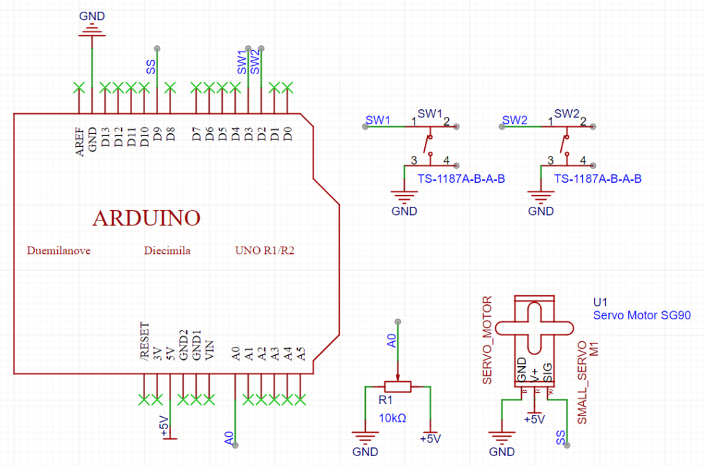
1. Conexión del servomotor (SG90)
- VCC (Rojo): → Arduino 5V
- GND (Marrón/Negro): → Arduino GND
- Señal (Naranja): → Digital Pin 9
2. Conexión del potenciómetro
- Uno exterior Pin: → Arduino 5V
- Otro exterior Pin: → Arduino GND
- Segundo Nombre Pin (Limpiaparabrisas): → Analógico Pin A0
3. Conexiones de botones
- Botón 1 (Aumentar ángulo):
- Una terminal → Digital Pin 2
- Otra terminal → GND
- Botón 2 (Disminuir ángulo):
- Una terminal → Digital Pin 3
- Otra terminal → GND
Tip: Utilice las resistencias pull-up internas de Arduino para los botones configurando su modo en ENTRADA_RETRAER.
💻 Código de ejemplo
A continuación se muestra un boceto de ejemplo que utiliza el potenciómetro como ángulo base y permite el ajuste con dos botones:
#include <Servo.h>

Servo myServo;  // Create a servo object

// Pin Definitions
const int servoPin = 9;        // Servo signal pin
const int potPin = A0;         // Potentiometer analog input
const int buttonUpPin = 2;     // Button to increase angle
const int buttonDownPin = 3;   // Button to decrease angle

int servoAngle = 90;  // Starting at the middle position (90°)

void setup() {
  Serial.begin(9600);
  myServo.attach(servoPin);  // Attach the servo to the defined pin

  // Set pin modes for the potentiometer (default INPUT) and buttons
  pinMode(potPin, INPUT);
  pinMode(buttonUpPin, INPUT_PULLUP);    // Enable internal pull-up resistor
  pinMode(buttonDownPin, INPUT_PULLUP);

  myServo.write(servoAngle);  // Set initial servo position
}

void loop() {
  // 1️⃣ Read the potentiometer value and map it to a 0-180° range
  int potValue = analogRead(potPin);
  int mappedAngle = map(potValue, 0, 1023, 0, 180);

  // Use the potentiometer value as the base servo angle
  servoAngle = mappedAngle;

  // 2️⃣ If the "increase" button is pressed, add 90° to the angle
  if (digitalRead(buttonUpPin) == LOW) {
    servoAngle += 90;
    if (servoAngle > 180) servoAngle = 180;
    delay(200);  // Debounce delay
  }

  // 3️⃣ If the "decrease" button is pressed, subtract 90° from the angle
  if (digitalRead(buttonDownPin) == LOW) {
    servoAngle -= 90;
    if (servoAngle < 0) servoAngle = 0;
    delay(200);  // Debounce delay
  }

  // 4️⃣ Update the servo with the new angle
  myServo.write(servoAngle);

  // Debug: Print the current angle to the Serial Monitor
  Serial.print("Angle: ");
  Serial.println(servoAngle);

  delay(20);  // Small delay for smooth operation
}
📋 Cómo funciona
- Potenciómetro:
Lee un valor analógico (0–1023) y lo asigna a un ángulo de servo (0°–180°). - Botones:
- Cuando la característica botón de aumento Se presiona el ángulo aumenta 90°.
- Cuando la característica botón de disminución se presiona, el ángulo disminuye 90°.
(Las resistencias pull-up internas y un retardo antirrebote ayudan a garantizar que las pulsaciones de los botones sean confiables).
- Servocontrol:
La posición del servo se actualiza continuamente según la lectura del potenciómetro y los ajustes del botón. - Monitoreo en serie:
El ángulo del servo actual se imprime con fines de depuración.
🎯 Cierre
Esta configuración te permite controlar un servo SG90 usando un potenciómetro (para un ajuste suave y continuo) y dos botones (para cambios rápidos e incrementales). ¡Es un gran proyecto para aprender a combinar entradas analógicas y digitales en Arduino!
¡Disfruta tu proyecto! 😊👍