A light-emitting diode (LED) can look bright while drawing only a few milliamperes. How can you find its current without opening the circuit or moving a probe into the meter’s current socket? Measure the voltage across its resistor, then use Ohm’s law.
What you will learn: how a resistor limits current, why voltage is measured between two points, and how one measurement can reveal a different electrical quantity. This experiment uses a regulated 5 V supply and a red indicator LED; no programming is needed.
Meet the two components
LED means light-emitting diode: a semiconductor component that produces light when current flows in its forward direction. Its two terminals are the anode and cathode. In this circuit the anode faces the resistor and positive supply; the cathode returns to the supply’s negative terminal. The bar in the diode symbol marks the cathode. Check the actual part’s datasheet if its leads have been trimmed.
A resistor opposes current flow. Its resistance is measured in ohms, written Ω. Here it prevents the supply from forcing too much current through the LED. The two components form a series circuit—one path, so the same current flows through both. The resistor can sit on either side of the LED in that path.
Parts for the experiment
- One regulated 5 V direct-current supply. DC means direct current; its polarity stays the same. If your supply has an adjustable current limit, set it to 20 mA.
- One red indicator LED rated for at least 20 mA continuous forward current. This example is for a small indicator, not a high-power lighting LED.
- 330 Ω, 680 Ω and 1 kΩ resistors, each rated at 0.25 W or more. One kilohm, kΩ, is 1,000 Ω; W means watt, the unit of power.
- A breadboard, jumper wires and a digital multimeter with a DC voltage range. A breadboard joins holes in internal groups; check its rail breaks before wiring.
Build and measure
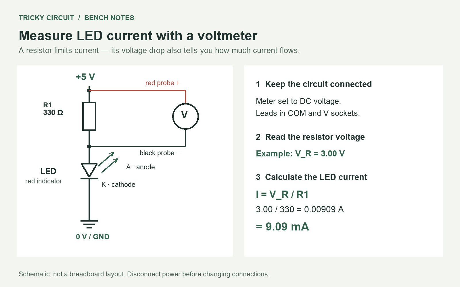
- Disconnect power. Connect supply positive → 330 Ω resistor → LED anode. Connect LED cathode → supply negative. GND means ground. The 0 V/GND symbol marks this circuit’s common reference, not a separate earth connection.
- Put the black meter lead in COM (common) and the red lead in the socket marked V or V/Ω. Select DC volts on a range that includes 5 V.
- Power the circuit. Measure the supply between its positive and negative terminals. Record the actual voltage.
- Measure across the resistor: red probe at its supply end, black probe at its LED end. Do not move either lead to a current socket for this experiment.
- Record the resistor voltage, V_R. Divide it by the resistor value to obtain the current, I:
I = V_R / R.
If you measure 3.00 V across 330 Ω, the current is 3.00 / 330 = 0.00909 A = 9.09 mA. A is ampere; a milliampere, mA, is one thousandth of an ampere. The LED voltage is then approximately 5.00 − 3.00 = 2.00 V, if the measured supply was exactly 5.00 V.
The voltmeter has a large input resistance and takes a small current of its own. With a typical 10 MΩ (megohm, or million-ohm) voltage input across 330 Ω, that effect is negligible for this beginner experiment. Check your meter’s specification if you need an accurate result.
Predict before changing the resistor
The table uses a fixed 2.0 V LED model and an exact 5.0 V supply. These are calculated examples, not measured results from a physical build. Real forward voltage changes with the part, current and temperature.
| Resistor | Predicted current | Resistor power |
|---|---|---|
| 330 Ω | 9.09 mA | 27.3 mW |
| 680 Ω | 4.41 mA | 13.2 mW |
| 1 kΩ | 3.00 mA | 9.0 mW |
Power in the resistor is P = V_R × I, or P = V_R² / R. A milliwatt, mW, is one thousandth of a watt. All three calculated values are well below a 0.25 W resistor rating.
Switch off before replacing the resistor. Try 680 Ω and then 1 kΩ, measure V_R each time, and calculate current from the measurement. Expect lower current and generally less light; your eyes do not judge brightness on a simple linear scale.
Three mistakes worth understanding
- Using 5 V in I = V/R. That is the supply voltage, not the voltage across the resistor. The LED uses part of the voltage too.
- Putting a meter in current mode across the supply. That can create a short circuit. This method deliberately keeps the meter in voltage mode and uses the resistor to infer current.
- Removing the resistor because the LED is “only 2 V.” Forward voltage is not a current regulator. Keep the series resistor; do not test an LED directly across 5 V.
Try it, then check your answer
Challenge 1: You measure 2.90 V across 680 Ω. What current flows? Challenge 2: You move the same resistor from the anode side to the cathode side, keeping the series path intact. Should the current change substantially?
Show the reasoning
1: 2.90 / 680 = 0.00426 A, about 4.26 mA. 2: The current should stay essentially the same. Both components are still in one series path. The locations of the measurement points change, but the circuit’s total voltage and components do not.
Continue in the interactive laboratory
Open Learn and choose 1 · First spark. Compare its current reading with your calculation. The laboratory uses a fixed 2 V LED model, so small differences from a real LED are expected. Its Circuitpedia link explains LED, current and circuit symbols.
For the component background, read What is a Resistor?. When you are ready to control the light in software, continue with connecting an LED to an Arduino.
Component reference
The Kingbright WP7113ID datasheet illustrates why an actual LED’s forward-voltage characteristics and ratings must be checked. The 2 V value above is a teaching assumption, not a guaranteed voltage for every red LED.