Two equal resistors across 5 V produce 2.5 V at their midpoint. Then you connect another component and the voltage falls. The resistors have not forgotten the formula: the connected component has changed the circuit.
What you will learn: how to calculate a loaded voltage divider, where its current goes, and why a divider is useful for signals but usually unsuitable for powering a device.
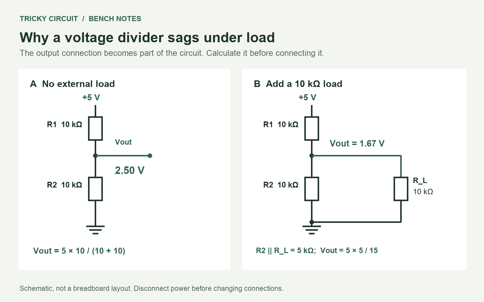
Understand the drawing
A voltage divider uses two series resistors to create an intermediate voltage. R1 connects to the positive supply, R2 connects to the common 0 V reference, and Vout means the output voltage at their junction, measured relative to that reference. The supply voltage is called Vin.
A node is a set of points joined by conducting wire. The dot marks a connected junction. A load is something drawing current from the output. We represent it with a third resistor, R_L. It connects to the same two nodes as R2, so they are in parallel. In the calculation, R2 || R_L means their combined parallel resistance.
Collect the parts
- A regulated 5 V direct-current (DC) supply: its positive and negative polarity stays the same.
- Two 10 kΩ resistors for R1 and R2. One kilohm, kΩ, equals 1,000 ohms; Ω is the symbol for ohm.
- 100 kΩ, 10 kΩ and 1 kΩ resistors to use as loads. Ordinary 0.25 W resistors are sufficient for the stated 5 V experiment.
- A breadboard, jumper wires and a digital multimeter set to DC voltage. Keep the black lead in COM (common) and the red lead in V (voltage).
First prediction: no external load
With nothing connected to Vout except an ideal voltmeter, the same current flows through both resistors:
I = Vin / (R1 + R2) = 5 / 20,000 = 0.00025 A = 0.25 mA
Here I is current, A means ampere, and mA means milliampere: one thousandth of an ampere. The voltage across R2 is:
Vout = Vin × R2 / (R1 + R2) = 5 × 10 / 20 = 2.50 V
The last expression uses kilohms in both numerator and denominator, so the units cancel. Do not mix 10 kΩ and 10,000 Ω as if they were different values.
Build it and add the load
- Disconnect power. Connect supply positive → R1 → output node → R2 → supply negative. Each resistor’s two leads must be in different connected groups on the breadboard.
- Power up and measure the supply. Then put the black voltage probe at supply negative and the red probe at the output node. With an actual 5.00 V supply and equal resistors, expect close to 2.50 V.
- Disconnect power. Add the third 10 kΩ resistor from the output node to supply negative. Leave R1 and R2 in place.
- Power up and measure Vout again. Expect close to 1.67 V, not 2.50 V.
A real voltmeter is itself a small load. For example, a 10 MΩ input across R2 gives about 2.49875 V rather than an ideal 2.50000 V. MΩ means megaohm, or one million ohms. Normal resistor tolerances and supply error may be larger effects; measure your actual parts if you want a closer prediction.
Why the voltage fell
The lower half is now two 10 kΩ resistors in parallel:
Rbottom = (R2 × R_L) / (R2 + R_L) = 5 kΩ
Use this new lower resistance in the divider formula:
Vout = 5 × 5 / (10 + 5) = 1.667 V
The upper current is approximately (5 − 1.667) / 10,000 = 0.333 mA. It splits into about 0.167 mA through R2 and 0.167 mA through the load. Current is conserved at the node. The added branch draws extra current through R1, increasing the voltage lost across R1 and leaving less voltage at Vout.
Try three different loads
Keep both divider resistors at 10 kΩ. Disconnect power before each change. These are calculated targets for ideal resistors, an exact 5 V supply and no meter loading; they are not bench measurements.
| External load R_L | Combined lower resistance | Predicted Vout |
|---|---|---|
| No external load | 10 kΩ | 2.500 V |
| 100 kΩ | 9.091 kΩ | 2.381 V |
| 10 kΩ | 5.000 kΩ | 1.667 V |
| 1 kΩ | 0.909 kΩ | 0.417 V |
Notice the direction: lower load resistance means more loading and a lower output voltage. Record the measured voltage beside each prediction and explain the differences before changing anything else.
Useful for a signal; unreliable as a power supply
A divider can scale a voltage for a measurement input. It cannot hold that voltage steady when a connected device’s current demand changes. A microcontroller or radio module may draw very different current during startup, sleep and transmission. Use a suitable voltage regulator when the job is to power such a device.
An analog-to-digital converter (ADC) turns an analog voltage into a digital number. Its input is not always equivalent to a single fixed resistor: some ADCs briefly draw current to charge an internal sampling capacitor. Texas Instruments explains this effect in its ADC input and sampling discussion. Check the particular device’s allowed input voltage and source-resistance requirements before connecting a divider to it.
Can you make the divider less sensitive?
Challenge: Replace R1 and R2 with 1 kΩ each, but keep the 10 kΩ load. Will Vout get closer to 2.5 V? What does that cost?
Show the calculation
The lower resistance becomes 1 kΩ || 10 kΩ = 0.909 kΩ. The output is 5 × 0.909 / (1 + 0.909) = 2.381 V, closer to 2.5 V. But the unloaded divider now draws 2.5 mA rather than 0.25 mA: ten times as much. Lower resistance improves this loading error by spending more supply current.
Continue experimenting
Open the interactive laboratory and choose 2 · Divide voltage. Toggle the load and watch the output change. Use 7 · Give current a choice to explore parallel branches, and the Circuitpedia link for resistor labels and units.
Read What is a Resistor? for component basics, or More Practical Applications of Resistors for other uses. Apply the load calculation from this experiment whenever something is connected to a divider’s output.