In electronics, “component biasing” or “support circuits” refers to the external components required for proper operation of a main component (e.g., microcontrollers, transistors, voltage regulators, op-amps). These supporting parts include resistors, capacitors, diodes, and inductors to ensure stability, filtering, and correct functionality.
Let’s break down the most common types of circuit support for different components! 🚀
1️⃣ Microcontroller Support Circuit 🧠
Example: ATmega328 (Arduino) or ESP32
📌 Key Support Components:
✅ Decoupling capacitors (0.1µF & 10µF) → Prevents power fluctuations.
✅ Pull-up resistors (10kΩ on RESET pin) → Ensures stable booting.
✅ External crystal oscillator (e.g., 16MHz with 22pF caps) → Provides clock signal.
✅ Voltage regulator (e.g., AMS1117 3.3V or 7805 5V) → Provides stable power.
⚡ Example Schematic:
🔹 ATmega328 Standalone Circuit
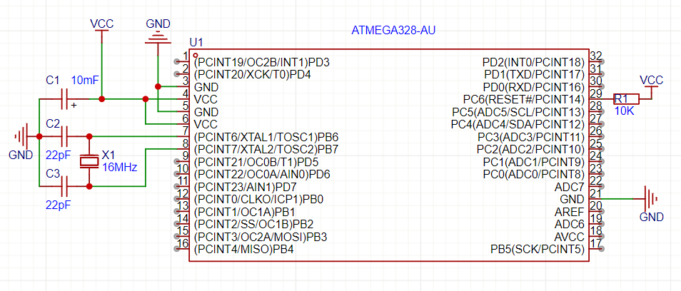
🔥 Without this support, the microcontroller might not boot or crash randomly!
2️⃣ Transistor Biasing ⚡
Example: NPN Transistor (BC547, 2N2222) or MOSFET (IRF540, IRLZ34N)
📌 Key Support Components:
✅ Base resistor (1kΩ – 10kΩ) → Limits current to protect the transistor.
✅ Pull-down resistor (10kΩ on Gate/Base) → Prevents floating state.
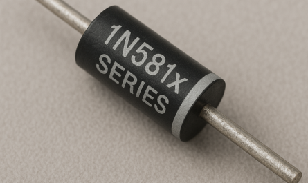
✅ Flyback diode (1N4007 for inductive loads) → Protects against voltage spikes.
⚡ Example NPN Transistor Circuit:

🔥 Without biasing, the transistor may not turn on/off properly or overheat!
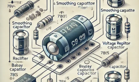
3️⃣ Voltage Regulator Stabilization 🔋
Example: 7805 (5V Regulator) or AMS1117 (3.3V Regulator)
📌 Key Support Components:
✅ Input capacitor (10µF) → Smooths incoming voltage.
✅ Output capacitor (1µF – 10µF) → Improves load response.
✅ Heatsink (for high current loads) → Prevents overheating.
⚡ Example 7805 Circuit:
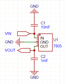
🔥 Without capacitors, the regulator may oscillate or provide unstable voltage!
4️⃣ Operational Amplifier Configuration 🎛️
Example: LM358, TL072, or OPA2134
📌 Key Support Components:
✅ Feedback resistor (R1, 10kΩ – 100kΩ) → Sets gain.
✅ Input resistor (R2, 1kΩ – 10kΩ) → Matches impedance.
✅ Decoupling capacitor (0.1µF – 10µF on power rails) → Reduces noise.
⚡ Example Inverting Op-Amp Configuration:
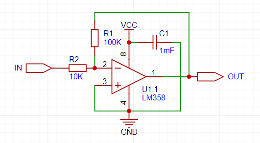
🔥 Without proper resistors, the op-amp won’t amplify correctly!
5️⃣ Crystal Oscillator Circuit ⏳
Example: 16MHz for ATmega328 or 8MHz for STM32
📌 Key Support Components:
✅ Load capacitors (22pF – 33pF) → Helps stabilize oscillation.
✅ Pull-down resistor (1MΩ) → Ensures proper startup.
⚡ Example 16MHz Crystal Circuit:
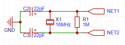
🔥 Without capacitors, the crystal might not oscillate properly!
6️⃣ Relay Driver Circuit ⚡
Example: Controlling a 5V/12V Relay with Arduino or ESP32
📌 Key Support Components:
✅ Flyback diode (1N4007) → Protects against back EMF.
✅ Transistor (2N2222 or IRF540) → Handles current switching.
✅ Base resistor (1kΩ) → Controls transistor switching.
⚡ Example Relay Control Circuit:
🔥 Without a flyback diode, the relay can generate high-voltage spikes and damage the transistor!
7️⃣ DC-DC Buck Converter Stabilization 🔄
Example: LM2596, XL4015, MP1584 (Step-Down Converters)
📌 Key Support Components:
✅ Inductor (22µH – 100µH) → Energy storage.
✅ Input capacitor (100µF) → Stabilizes input voltage.
✅ Output capacitor (100µF) → Reduces ripple noise.
✅ Diode (Schottky 1N5819) → Prevents reverse current.
⚡ Example LM2596 Circuit:
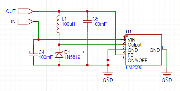
🔥 Without proper capacitors, the output may have noise and instability!
🚀 Summary – Why Component Biasing is Crucial!
✔ Ensures components operate correctly.
✔ Protects circuits from voltage spikes & noise.
✔ Prevents overheating and failure.
✔ Improves efficiency & stability.
⚡ Every component needs proper biasing and support elements! Ignoring them can lead to failures, noise, or unstable circuits.