A relay module allows an Arduino to control high-voltage devices like lights, fans, motors, or home appliances. Since Arduino operates at low voltage (3.3V/5V) and cannot directly switch high-power loads, a relay acts as an electrically isolated switch.
🔹 1. How a Relay Module Works
A relay module consists of:
- Electromagnetic Relay – A switch that opens or closes when powered.
- Optocoupler (for isolation) – Prevents high-voltage backflow to Arduino.
- Transistor (Driver Circuit) – Controls the relay using a small current.
- Diode (Flyback Protection) – Prevents voltage spikes when turning off the coil.
- Indicator LED – Shows relay status.
📌 Function:
- When the Arduino sends a signal (HIGH or LOW), the relay activates or deactivates.
- The relay can switch AC (110V/220V) or DC (12V/24V) loads.
🔹 2. Relay Module Types
| Relay Type | Description |
|---|---|
| Single-Channel Relay | Controls one high-power device |
| 2/4/8-Channel Relay | Controls multiple devices |
| Mechanical Relay | Standard electromechanical switch |
| Solid-State Relay (SSR) | Faster, silent switching (no mechanical parts) |
🔹 3. Relay Module Pinout
A typical relay module has 5 pins:
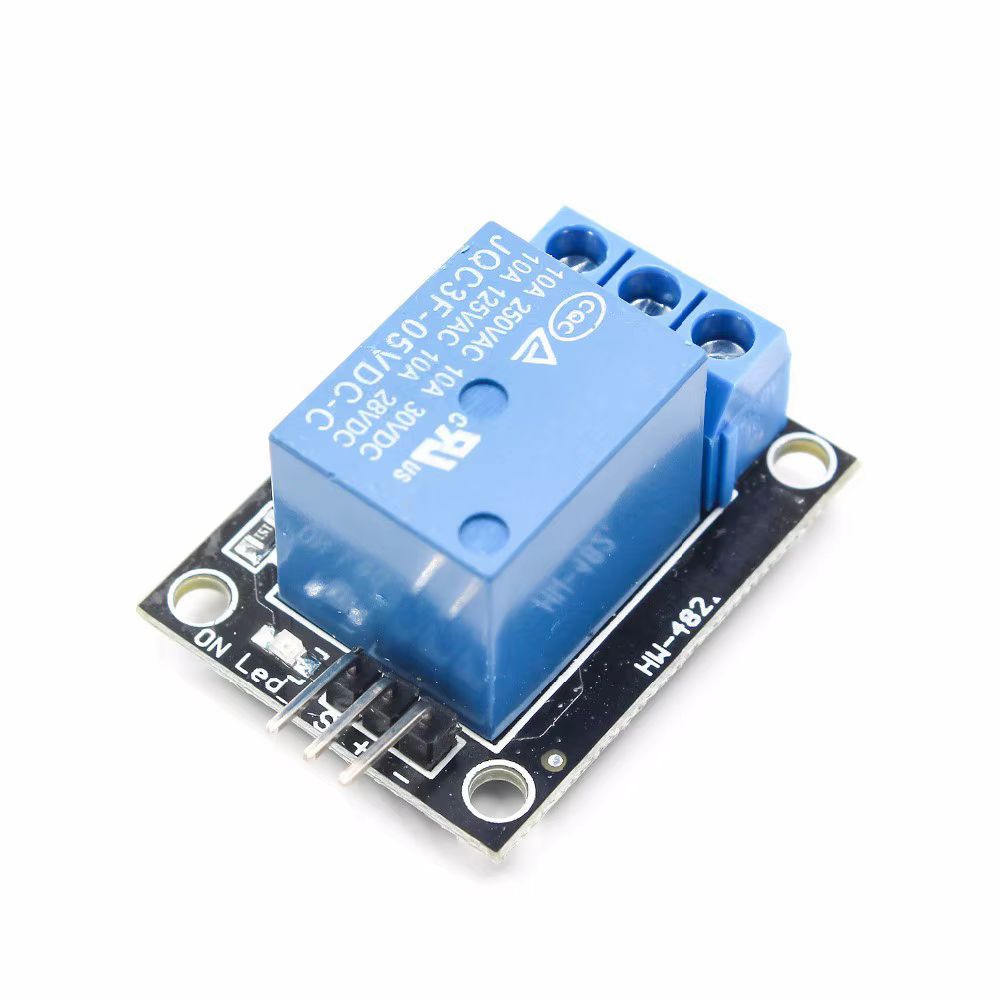
| Relay Pin | Function |
|---|---|
| VCC | Power (5V) |
| GND | Ground |
| IN | Control pin (Arduino Digital Output) |
| COM (Common) | Shared terminal |
| NO (Normally Open) | Open when relay is OFF, closed when ON |
| NC (Normally Closed) | Closed when relay is OFF, open when ON |
📌 “Normally Open” (NO) → Device is OFF by default, turns ON when relay is activated.
📌 “Normally Closed” (NC) → Device is ON by default, turns OFF when relay is activated.
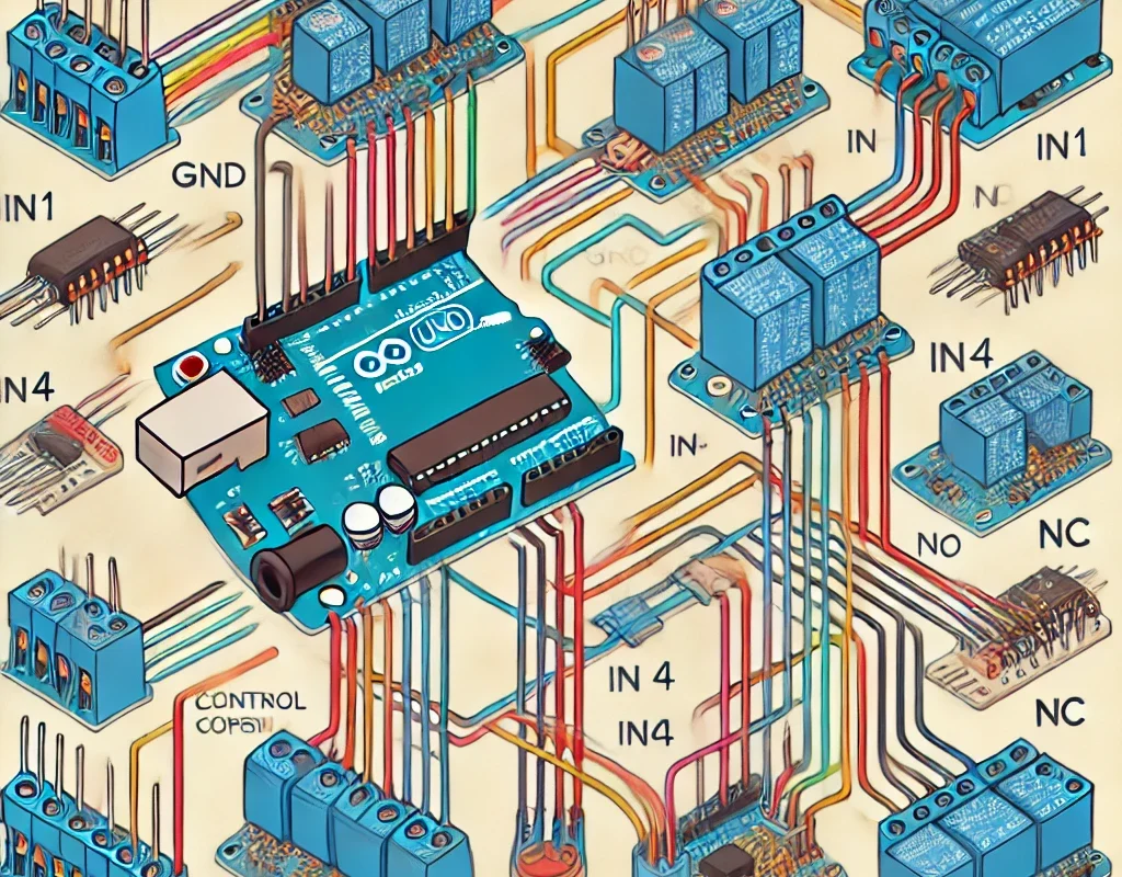
🔹 4. Connecting a Relay Module to Arduino
🛠 Required Components
- 1x Arduino Board (Uno, Mega, Nano, etc.)
- 1x Relay Module (5V)
- 1x 220V Lamp (or 12V DC Motor)
- Jumper Wires
- External Power Source (if needed)
🛠 Wiring Diagram
| Relay Pin | Arduino Pin |
|---|---|
| VCC | 5V |
| GND | GND |
| IN | D7 |
High-Voltage Load Connection (AC Example):
- COM → Live Wire (from Power Source)
- NO → Load (Lamp, Fan, Motor)
- Neutral Wire → Directly to Load
🔹 5. Arduino Code for Relay Control
This basic example turns a relay ON for 5 seconds, then turns it OFF for 5 seconds.
#define RELAY_PIN 7  // Relay connected to Digital Pin 7

void setup() {
    pinMode(RELAY_PIN, OUTPUT);
}

void loop() {
    digitalWrite(RELAY_PIN, HIGH); // Turn ON Relay
    delay(5000);                   // Wait 5 seconds
    digitalWrite(RELAY_PIN, LOW);  // Turn OFF Relay
    delay(5000);                   // Wait 5 seconds
}
📌 For Active-Low Relays (some modules work in reverse):
- Use
LOWto turn ON andHIGHto turn OFF.
🔹 6. Controlling a Relay with a Sensor
Example: Turn on a light when it’s dark (using LDR sensor).
#define RELAY_PIN 7
#define LDR_PIN A0

void setup() {
    pinMode(RELAY_PIN, OUTPUT);
    pinMode(LDR_PIN, INPUT);
}

void loop() {
    int lightValue = analogRead(LDR_PIN);  // Read LDR sensor
    if (lightValue < 500) {  // If it's dark
        digitalWrite(RELAY_PIN, HIGH);  // Turn ON relay
    } else {
        digitalWrite(RELAY_PIN, LOW);  // Turn OFF relay
    }
}
📌 Other Relay Applications:
✅ Temperature-Based Control (DHT11 + Relay for Fan).
✅ Motion Detection (PIR Sensor + Relay for Security Light).
✅ Wi-Fi Home Automation (ESP8266 + Relay).
🔹 7. Safety Precautions When Using Relays
⚠️ Avoid Directly Touching High-Voltage Wires.
⚠️ Use Relays with Optocouplers for Electrical Isolation.
⚠️ Do Not Exceed the Relay’s Rated Voltage/Current.
⚠️ For AC Loads, Use Proper Insulation & Fuse Protection.
🎯 Conclusion
- A relay module allows Arduino to control high-voltage appliances.
- It works by switching AC or DC loads using a small control signal.
- Can be used for home automation, security, and industrial applications.
- Always follow safety guidelines when working with high voltage.