
Key Features:
- Type: DC gear motor.
- Voltage: Typically operates at 3V to 6V.
- Speed: These motors usually offer speeds ranging from 100 RPM to 200 RPM when running at 6V, though this can vary depending on the specific model and voltage.
- Torque: The gearbox reduces the speed but increases the torque, making them powerful enough to drive the wheels or tracks of small robots.
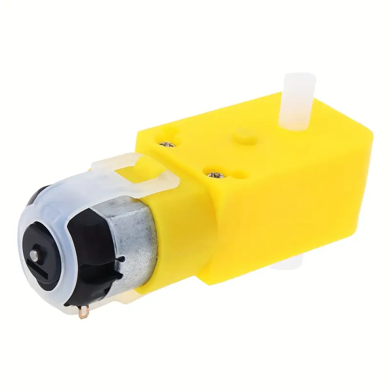
Construction:
- Gearbox: Attached to the motor is a reduction gearbox. The most common configurations are plastic gears, which help reduce the cost and are sufficiently robust for light-duty applications.
- Motor Shaft: The output shaft from the gearbox usually has a double-flat or cross-cut profile, which makes attaching wheels, gears, or other mechanisms easy without the need for additional couplings.
- Size: Compact and easy to mount in small projects. Dimensions can vary slightly but are generally small enough for use in miniature robotics.
Applications:
- Educational Robotics: Widely used in educational kits for schools and workshops to teach basic robotics and engineering concepts.
- DIY Projects: Ideal for DIY enthusiasts building simple robotic vehicles or mechanisms.
- Hobbyist Projects: Common in hobbyist projects where cost, size, and ease of use are important factors.
Wiring and Control:
- Simple DC Operation: These motors can be driven by basic DC voltage from batteries, or controlled via a motor driver connected to a microcontroller like an Arduino to allow for more advanced functions like speed and direction control.
- Motor Driver Compatibility: Compatible with a variety of motor drivers, which can provide the necessary protection and control for direction and speed.
Example Setup with Arduino:
Here’s a simple example of how you can control a TT motor using an Arduino and a basic motor driver (like the L298N or L293D):
Circuit Components:
- Arduino Board
- TT Motor
- Motor Driver (e.g., L298N, L293D)
- External Power Supply (if required by the motor driver)
- Jumper wires
Basic Wiring Guide:
- Connect the Motor to the Motor Driver: Attach the motor terminals to the outputs on the motor driver module.
- Connect the Motor Driver to Arduino:
- Connect the input pins on the motor driver to the Arduino digital pins.
- Connect the enable pin on the motor driver to a PWM-capable pin on the Arduino if you want to control motor speed.
- Power Supply:
- Provide power to the motor driver. If using a model like the L298N, it might require a higher voltage, which should be connected to its dedicated power input.
- Ensure the ground of the Arduino is connected to the ground of the motor driver.
- Programming:
- Write a simple sketch to control the motor via the Arduino, using
digitalWrite()to set direction andanalogWrite()to control speed if using PWM.
- Write a simple sketch to control the motor via the Arduino, using
// Example Arduino Code for Controlling a TT Motor
int motorPin1 = 3; // Motor pin 1 connected to digital pin 3
int motorPin2 = 4; // Motor pin 2 connected to digital pin 4
int enablePin = 5; // PWM pin for speed control

void setup() {
    pinMode(motorPin1, OUTPUT);
    pinMode(motorPin2, OUTPUT);
    pinMode(enablePin, OUTPUT);
}

void loop() {
    digitalWrite(motorPin1, HIGH); // Set motor direction
    digitalWrite(motorPin2, LOW);
    analogWrite(enablePin, 128); // Set speed (0-255)
    delay(1000);
    digitalWrite(motorPin1, LOW); // Reverse direction
    digitalWrite(motorPin2, HIGH);
    delay(1000);
}
TT motors are a great choice for those starting out in robotics or for any project where size, cost, and simplicity are key considerations.