Tinkercad Circuits allows you to design, simulate, and test electronic circuits before building them physically. Below is a step-by-step guide on how to create a circuit design in Tinkercad.
🔹 1. Getting Started with Tinkercad Circuits
Step 1: Create an Account
- Go to Tinkercad.
- Click Sign Up (or Log In if you already have an account).
- Choose “Circuits” from the main dashboard.
Step 2: Create a New Circuit
- Click “Create New Circuit”.
- The workspace opens with a grid-based canvas where you can drag and place components.
🔹 2. Adding Components
Step 3: Select Components
- On the right, click the “Components” panel.
- Choose from basic or all components (for more advanced parts).
- Common components include:
- Arduino Uno
- Resistors
- LEDs
- Motors & Relays
- Sensors (DHT11, IR, Ultrasonic, etc.)
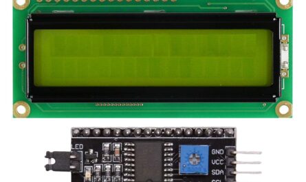
- LCD Displays
- Breadboard
Step 4: Drag and Drop Components
- Click on a component and drag it into the workspace.
- Rotate or move it as needed using the Move Tool.
🔹 3. Wiring the Circuit
Step 5: Connect Components with Wires
- Click on a pin to create a wire.
- Drag the wire to another pin to make a connection.
- Use different colors for organization:
- Red = Power (VCC, 5V)
- Black = Ground (GND)
- Blue/Green = Data or Signal
Step 6: Use a Breadboard (Optional)
- If your circuit requires multiple connections, use a breadboard.
- Connect VCC to the power rail and GND to the ground rail.
🔹 4. Writing Code for Arduino-Based Circuits
Step 7: Open the Code Editor
- If using an Arduino, click “Code” > Choose “Blocks + Text” or “Text” (C++).
Step 8: Write Arduino Code
Example Blinking LED using Arduino:
void setup() {
  pinMode(13, OUTPUT);  // Set pin 13 as an output
}

void loop() {
  digitalWrite(13, HIGH);  // Turn LED on
  delay(1000);             // Wait 1 second
  digitalWrite(13, LOW);   // Turn LED off
  delay(1000);             // Wait 1 second
}
Step 9: Simulate the Circuit
- Click “Start Simulation”.
- If using Arduino, check the Serial Monitor for debugging.
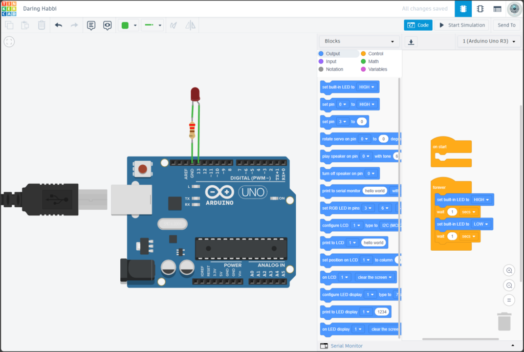
🔹 5. Example: Simple LED Circuit Design
🛠 Required Components
- 1x LED
- 1x Resistor (220Ω)
- 1x Arduino Uno
- Jumper Wires
🛠 Circuit Wiring
| Component | Arduino Pin |
|---|---|
| LED Anode (+) | D13 |
| LED Cathode (-) | GND |
| Resistor (220Ω) | Between LED Anode and D13 |
🛠 Simulation
- Run the simulation, and the LED will blink every second.
🔹 6. Saving and Exporting Your Design
Step 10: Save the Circuit
- Click “Save” (Tinkercad automatically saves progress).
Step 11: Export the Design
- You can export the circuit as a PNG image or schematic.
- Click “Export” → Choose .brd (Eagle) for PCB design.
🔹 7. Advanced Features in Tinkercad Circuits
✅ Use Sensors & Modules – DHT11, IR sensors, LCD displays, motors.
✅ Work with Logic Gates – Create AND, OR, NOT circuits.
✅ Simulate Serial Communication – Send data to the Serial Monitor.
✅ Multi-Board Circuits – Use multiple Arduino boards in one circuit.
🎯 Conclusion
Tinkercad Circuits is a powerful tool for designing, simulating, and testing electronics projects. Whether you’re learning Arduino, prototyping circuits, or designing projects, it’s a great way to test ideas before building them physically.