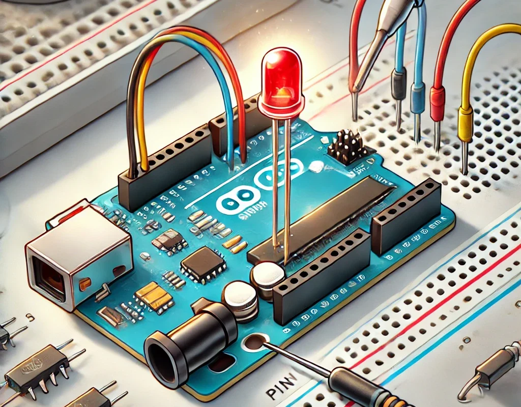
Connecting an LED to an Arduino is simple, but there are best practices to ensure safe operation and proper brightness control. Below are different ways to connect an LED to an Arduino while avoiding common mistakes.
🔹 1. Basic LED Connection (with a Resistor)
🛠 Required Components
- 1x Arduino (Uno, Mega, Nano, etc.)
- 1x LED (any color)
- 1x Resistor (220Ω – 1kΩ)
- Jumper wires
🛠 Wiring:
| Component | Connection |
|---|---|
| LED Anode (+, long leg) | Arduino Digital Pin (e.g., D7) |
| LED Cathode (-, short leg) | Resistor (220Ω – 1kΩ) → GND |
📌 Why use a resistor?
- Limits current to prevent LED burnout.
- Typical LED current should be 5mA – 20mA.
- For a 5V Arduino, a 220Ω – 1kΩ resistor is recommended.
✅ Example Arduino Code: Blink an LED
#define LED_PIN 7  // LED connected to pin 7

void setup() {
    pinMode(LED_PIN, OUTPUT);
}

void loop() {
    digitalWrite(LED_PIN, HIGH);  // Turn LED ON
    delay(1000);  // Wait 1 second
    digitalWrite(LED_PIN, LOW);   // Turn LED OFF
    delay(1000);
}
📌 What happens?
- The LED blinks ON and OFF every second.
🔹 2. Controlling LED Brightness with PWM (Analog Output)
📌 PWM (Pulse Width Modulation) allows brightness control by adjusting how long the LED is ON vs. OFF.
🛠 Wiring (Same as Basic Setup)
- Connect the LED to a PWM-capable pin (D3, D5, D6, D9, D10, D11 on Arduino Uno).
- Use a 220Ω – 1kΩ resistor.
✅ Example Arduino Code: LED Fade Effect
#define LED_PIN 9  // PWM-capable pin

void setup() {
    pinMode(LED_PIN, OUTPUT);
}

void loop() {
    for (int brightness = 0; brightness <= 255; brightness++) {
        analogWrite(LED_PIN, brightness);  // Increase brightness
        delay(10);
    }
    for (int brightness = 255; brightness >= 0; brightness--) {
        analogWrite(LED_PIN, brightness);  // Decrease brightness
        delay(10);
    }
}
📌 What happens?
- The LED gradually increases and decreases in brightness.
🔹 3. Connecting Multiple LEDs to Arduino
📌 You can control multiple LEDs individually or in a sequence.
✅ Example: Blinking Multiple LEDs
#define LED1 5
#define LED2 6
#define LED3 7

void setup() {
    pinMode(LED1, OUTPUT);
    pinMode(LED2, OUTPUT);
    pinMode(LED3, OUTPUT);
}

void loop() {
    digitalWrite(LED1, HIGH);
    delay(500);
    digitalWrite(LED1, LOW);

    digitalWrite(LED2, HIGH);
    delay(500);
    digitalWrite(LED2, LOW);

    digitalWrite(LED3, HIGH);
    delay(500);
    digitalWrite(LED3, LOW);
}
📌 What happens?
- Each LED blinks in sequence every 0.5 seconds.
🔹 4. Using a Transistor to Control High-Power LEDs
📌 If you want to control a high-power LED (e.g., 12V LED strips or 1W/3W LEDs), an Arduino cannot directly provide enough current.
🛠 Required Components
- 1x NPN Transistor (e.g., BC547, 2N2222, TIP120)
- 1x 1kΩ Resistor (Base Resistor)
- 1x High-Power LED or LED Strip (12V)
- 1x External 12V Power Supply
🛠 Wiring
| Component | Connection |
|---|---|
| LED Anode | +12V Power Supply |
| LED Cathode | Transistor Collector |
| Transistor Emitter | GND |
| Transistor Base | Arduino PWM Pin (through 1kΩ Resistor) |
✅ Example Code: PWM Control for High-Power LED
#define LED_PIN 9  // Connect to transistor base via 1kΩ resistor

void setup() {
    pinMode(LED_PIN, OUTPUT);
}

void loop() {
    analogWrite(LED_PIN, 128);  // 50% Brightness
    delay(2000);
    analogWrite(LED_PIN, 255);  // 100% Brightness
    delay(2000);
}
📌 Why use a transistor?
- Arduino cannot handle high-current loads.
- A transistor allows the Arduino to control high-power LEDs with an external power source.
🔹 5. Using a MOSFET for Controlling LED Strips
📌 For RGB LED strips, a MOSFET (IRLZ34N, IRF540N) is a better option than a transistor.
🛠 Wiring for MOSFET Control
| Component | Connection |
|---|---|
| LED Strip + | 12V Power Supply |
| LED Strip – | MOSFET Drain |
| MOSFET Source | GND |
| MOSFET Gate | Arduino PWM Pin (through 220Ω Resistor) |
✅ Example Code for RGB LED Strip
#define RED_PIN 9
#define GREEN_PIN 10
#define BLUE_PIN 11

void setup() {
    pinMode(RED_PIN, OUTPUT);
    pinMode(GREEN_PIN, OUTPUT);
    pinMode(BLUE_PIN, OUTPUT);
}

void loop() {
    analogWrite(RED_PIN, 255);  // Full Red
    analogWrite(GREEN_PIN, 0);
    analogWrite(BLUE_PIN, 0);
    delay(1000);

    analogWrite(RED_PIN, 0);
    analogWrite(GREEN_PIN, 255);  // Full Green
    delay(1000);

    analogWrite(RED_PIN, 0);
    analogWrite(GREEN_PIN, 0);
    analogWrite(BLUE_PIN, 255);  // Full Blue
    delay(1000);
}
📌 What happens?
- The RGB LED strip cycles through Red, Green, and Blue colors.
🔹 6. Common Mistakes When Connecting LEDs
❌ Connecting an LED without a resistor → Can burn out the LED or damage the Arduino pin.
✅ Always use a resistor (220Ω – 1kΩ) to limit current.
❌ Connecting a high-power LED directly to an Arduino → Can overload the Arduino’s pin.
✅ Use a transistor or MOSFET to control high-current LEDs.
❌ Using a wrong MOSFET (high gate threshold voltage) → Will not turn on fully with Arduino’s 5V.
✅ Use a logic-level MOSFET (e.g., IRLZ34N) that works with 5V logic.
🎯 Conclusion
- Basic LEDs can be connected with a resistor directly to Arduino.
- PWM allows brightness control (use
analogWritefor smooth fading). - For multiple LEDs, use sequential programming or shift registers.
- For high-power LEDs, use a transistor (BC547, TIP120) or MOSFET (IRLZ34N, IRF540N).
- For LED strips, use a MOSFET to control brightness and color.

