
A four-wire fan has a power connection, a command input and a separate speed output. Changing a number in a program does not establish that the rotor reached that speed. Build a small bench controller that keeps the motor supplied with steady power, generates a defined command waveform and releases the control wire when the experiment ends.
Choose the exact fan and separate the four jobs
Use an original Noctua NF-A4x10 5V PWM, an original Raspberry Pi Pico Rev3 with RP2040, and official MicroPython 1.26.0 for RPI_PICO. The fan name includes both 5V and PWM. The three-wire NF-A4x10 5V and the 12 V NF-A4x10 PWM are different variants. A connector that fits does not establish the correct supply voltage.
Pulse-width modulation (PWM) changes the fraction of each repeating cycle spent at the high logic level. Duty cycle names that fraction. It does not mean repeatedly disconnecting this fan’s power supply. Revolutions per minute (RPM) describe mechanical rotation. The command pin requests behavior; the tachometer output reports motion through a different wire. This article deliberately leaves the tachometer unconnected, so the program cannot truthfully report RPM.
The supporting interface is a Texas Instruments SN74AHCT125N in the 14-pin plastic dual in-line package (PDIP), powered by the same regulated 5 V rail as the fan. Its first gate is a noninverting buffer: an enabled output actively drives both high and low. Its separate output-enable input, written /OE, is active low. High /OE disconnects that output electrically; this is called a high-impedance state. It is different from actively driving low.
One onsemi 2N3904BU in the Transistor Outline (TO-92) package controls /OE, not the fast PWM signal. NPN names its semiconductor layer sequence. Here its base receives a small control current, its collector pulls /OE low, and its emitter joins ground. Keeping the NPN on the slow enable path avoids using an open-collector transistor as the actual fan waveform driver. Noctua specifically cautions that a weak internal pull-up can distort that arrangement.
- A regulated 5.00 V supply held within 4.90–5.10 V, initially current-limited to 0.20 A; Universal Serial Bus (USB) powers the Pico separately. Connect the returns together. Do not connect the external 5 V rail to the Pico’s 3V3 pin.
- U1 SN74AHCT125N, Q1 2N3904BU, R1 = 47 Ω ±5%, R2 = 1 kΩ ±5%, R3 = 1 kΩ ±5%, R4 = 100 kΩ ±5%, R5 = 10 kΩ ±5%.
- C1 = 100 nF ceramic beside U1’s supply pins, C2 = 100 µF electrolytic rated at least 10 V beside the fan connector. C2’s positive lead goes to +5 V. These are local bypass/reservoir parts, not a verified cure for every supply transient.
- A short four-pin fan extension or breakout with confirmed numbered contacts; short breadboard connections. A meter checks static rails. An oscilloscope is needed to verify frequency, voltage, edges and overshoot at the fan input.
V denotes volts, A amperes and Ω ohms. Prefixes k, m, µ and n mean thousand, thousandth, millionth and billionth respectively; for example, 1 kΩ is 1,000 ohms. Hertz (Hz) counts cycles per second.
Wire the motor power and logic paths separately
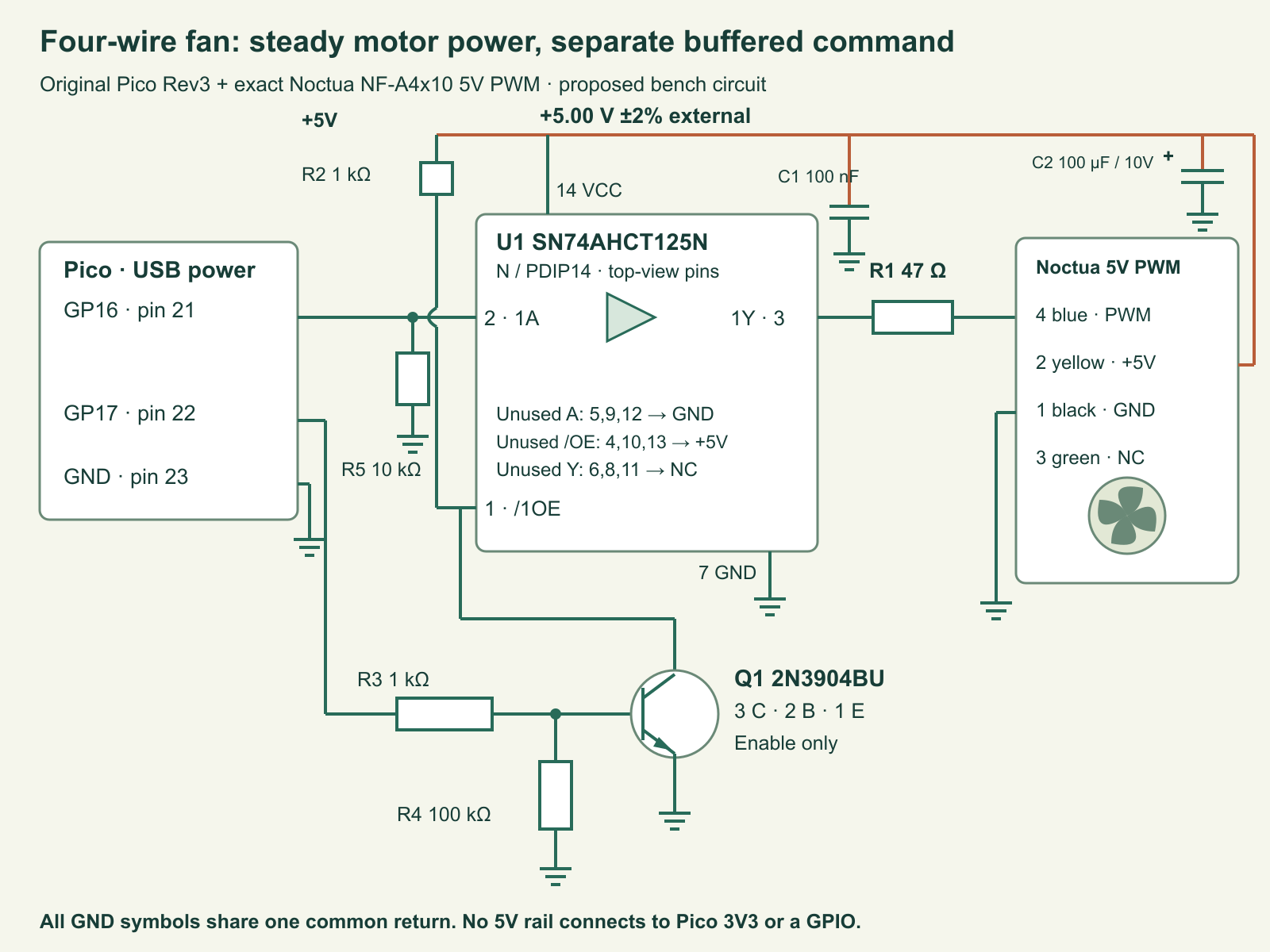
| Connection | Exact destination | Purpose |
|---|---|---|
| External +5 V / common return | Fan pin 2 yellow / pin 1 black; U1 pin 14 / pin 7 | Continuous motor and buffer supply; common logic reference. |
| Pico GP16, physical pin 21 | U1 pin 2, 1A; R5 from that junction to ground | 3.3 V PWM data, with a defined low state while the Pico pin is inactive. |
| U1 pin 3, 1Y | Through R1 to fan pin 4 blue | Buffered command; the resistor adds modest edge damping. |
| U1 pin 1, /1OE | R2 to +5 V and Q1 collector pin 3 | Default disconnected output; pulled low only when enabled. |
| Pico GP17, physical pin 22 | R3 to Q1 base pin 2; R4 base to emitter | Enable command and base discharge/default-off path. |
| Q1 emitter pin 1; Pico GND pin 23 | Common return | Closes the control circuit without putting 5 V on a Pico input. |
| Unused buffer gates | /OE pins 4, 10, 13 to +5 V; A pins 5, 9, 12 to ground; Y pins 6, 8, 11 open | Defined unused inputs and disconnected unused outputs. |
| Fan pin 3 green | Unconnected and insulated | Tachometer output is outside this command-only experiment. |
Ground is the shared zero-volt return, not an isolation barrier. Confirm fan contacts by their numbered connector positions and the exact product documentation; wire colours are supporting evidence for this model. Confirm Q1 lead numbers from onsemi’s drawing, rather than the familiar outline of another TO-92 transistor. The 5 V /OE junction is never wired directly to a Pico GPIO. General-purpose input/output (GPIO) is the configurable digital pin function; a pin number is not a voltage converter.
With both sources off, continuity-check each net and inspect supply rail breaks. Connect ground first. Turn on the current-limited 5 V rail and confirm its voltage before starting Pico control. Initially Q1 is off, R2 makes /OE high and the buffer releases the fan input. Noctua specifies full-speed behavior when no command is connected. That intended default depends on actual wiring and powered, functioning parts; it is not a guarantee against a shorted transistor, missing ground, stalled rotor or supply loss.
Calculate the electrical conditions before commanding speed
The exact fan specifies up to 0.07 A at its 5 V power input, approximately 0.35 W. The supply supplies that motor current. A GPIO and a buffer signal output do not. The 0.20 A bench current limit leaves room above that stated current but is not a characterization of starting transients. If the supply remains in current limit or the rail sags, stop and resolve the cause before interpreting a command trial.
TI’s SCLS264R datasheet, revised February 2024, gives U1 a recommended supply range of 4.5–5.5 V and a 2.0 V minimum high input threshold. Its TTL-compatible input threshold allows a 3.3 V Pico output to control a buffer powered at 5 V. TTL means transistor-transistor logic; it describes the compatible input levels here, not the construction of the entire chip. A similar-looking 74HC125 must not be substituted on that name alone: its input requirements differ.
Noctua’s PWM input requires a low level below 0.8 V. Using TI’s 0.44 V maximum low-output figure at the specified 8 mA test condition as a conservative budgeting point, and allocating 5 mA to the fan input, R1’s +5% endpoint adds 0.005 × 49.35 ≈ 0.247 V. The sum is approximately 0.687 V, below 0.8 V. This budget is not a measured low voltage or edge guarantee. It uses the correct recommended output-current region; the separate absolute maximum ratings are stress limits.
R2 draws approximately 5 V / 1 kΩ = 5 mA while Q1 is on. Taking a nominal 0.8 V base-emitter drop, R3 supplies about (3.3 − 0.8) / 1 kΩ = 2.5 mA before the small R4 share. That is a deliberately strong base drive for the small enable load, not the fan motor current. The transistor’s tabulated saturation tests have their own current and temperature conditions: do not claim the exact on-state voltage here from a different test row.
The 5 V rail’s chosen upper endpoint is 5.10 V, below the PWM input’s separate 5.25 V absolute voltage boundary. This does not authorize operating at the boundary or tolerate overshoot. Keep the circuit short and verify the signal at the fan with a suitable scope probe. The buffer’s supply range alone is not the complete system limit.
U1 also requires fast input transitions, including at /OE: TI lists a maximum 20 ns/V input transition rate. R2 is deliberately 1 kΩ rather than a very weak pull-up so that the enable node can charge its input, transistor and wiring capacitance quickly. That improves a proposed circuit; it does not measure its rise time. Keep the /OE wiring short and inspect its rising and falling edges with the scope as well as the PWM output. A resistance-capacitance (RC) estimate based on guessed capacitance cannot certify compliance.
One duty cycle, two quite different meanings
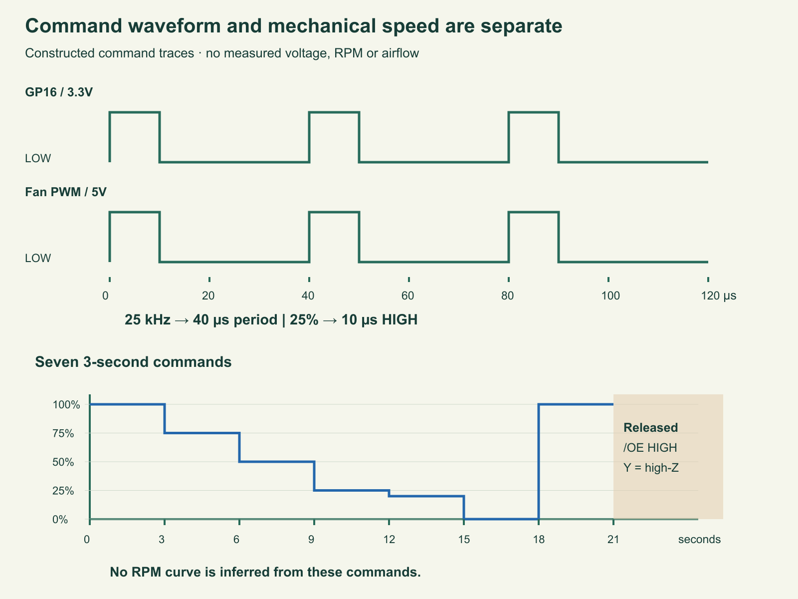
The requested frequency is 25 kHz, so the nominal period is 1 / 25,000 = 40 µs. A 25% command is high for 10 µs and low for 30 µs in each ideal cycle. The enabled AHCT125 gate does not invert it. Q1 inverts the enable control only: GP17 high pulls /OE low. Confusing these two paths can reverse the expected command.
The fan accepts 21–28 kHz according to its control documentation. The program checks the frequency reported by the PWM driver against that interval. A driver-reported value is not an independent scope measurement. MicroPython’s 16-bit duty argument also does not promise 16 effective bits at every frequency. The hardware uses finite clock divisors and counter steps; oscillator error, edge shape and the actual load remain to be checked.
For a percent command p, the program uses round(p × 65,535 / 100) with integer arithmetic. At 50%, that produces 32,768, a ratio just above one half. At 20%, it produces 13,107 exactly. Neither number is a measurement of speed. Noctua gives this model specific 20% and maximum-speed points, but we do not fit those endpoints into a calibrated RPM transfer function. A mechanical load, mounting or fault can change the observed result.
Normal running steps are 20–100%. A separate 0% step is included because the exact selected fan specifies stopping at zero; arbitrary sub-20% settings are refused rather than presented as a defined operating region. These facts do not transfer to every four-wire fan. Full command is also different from released output: the first actively drives high through U1; the second lets the powered fan establish its own input level.
Complete bounded command experiment
Save the following as pico_fan_pwm_command.py on the Pico and run it manually after inspecting the circuit. This is the ordinary Python-source workflow on the pinned MicroPython release; a host test has not produced a target firmware binary. Keep GPIO16’s PWM slice free of other PWM experiments, because changing a shared generator can change another channel’s frequency.
The sequence lasts seven holds of three seconds: 100, 75, 50, 25, 20, 0 and 100 percent. The complete list is validated before touching GPIO. The output is initially disabled, the PWM peripheral is configured, its reported frequency is checked and only then is the buffer enabled. An exception enters cleanup. Cleanup first attempts to disable U1, then deinitializes PWM and clears the data pin. If a cleanup operation fails, the program explicitly prints CLEANUP_UNVERIFIED; software cannot prove a wire’s physical voltage from a failed API call.
Download the complete program (ZIP; file: tricky-circuit-batch-007/code/pico_fan_pwm_command.py). Its full source is also below.
Complete Python program
"""Noctua NF-A4x10 5V PWM bench command experiment, Pico / MicroPython 1.26.

5V SN74AHCT125N channel1 buffers GP16. GP17 drives a 2N3904 through 1 kohm
to pull /OE low; its 100 kohm base pulldown releases /OE on reset. The 1 kohm
/OE pullup disables output. This program reports commands, never measured RPM.
Use only the article's complete circuit and power sequence.
"""

PWM_HZ = 25_000
COMMANDS = (100, 75, 50, 25, 20, 0, 100)


def command_code(percent):
    """Accept exact integer 0 or 20..100; unsupported sub20 operation is refused."""
    if type(percent) is not int or not (percent == 0 or 20 <= percent <= 100):
        raise ValueError("Use integer 0, or 20..100; this is a command, not RPM")
    return (percent * 65535 + 50) // 100


def validate_sequence(commands, hold_ms):
    commands = tuple(commands)
    if not commands or len(commands) > 16:
        raise ValueError("Choose 1..16 bounded command steps")
    if type(hold_ms) is not int or not 1000 <= hold_ms <= 10_000:
        raise ValueError("Hold each step for 1000..10000 ms")
    for percent in commands:
        command_code(percent)
    return commands


def release(enable, pwm, signal, output_mode):
    """Attempt every cleanup, disable first. Errors are visible, not proof of release."""
    failures = []
    actions = []
    if enable is not None:
        actions.append(("disable", lambda: enable.value(0)))
    if pwm is not None:
        actions.append(("pwm_deinit", pwm.deinit))
    if signal is not None:
        actions.append(("signal_low", lambda: signal.init(output_mode, value=0)))
    for name, action in actions:
        try:
            action()
        except Exception as exc:
            failures.append((name, type(exc).__name__))
    return failures


def run(Pin, PWM, sleep_ms, write=print, commands=COMMANDS, hold_ms=3000):
    """Dependency injection permits host fault checks of this same control flow."""
    commands = validate_sequence(commands, hold_ms)
    enable = signal = pwm = None
    try:
        # /OE stays HIGH until a valid waveform is already configured.
        enable = Pin(17, Pin.OUT, value=0)
        signal = Pin(16, Pin.OUT, value=0)
        pwm = PWM(signal, freq=PWM_HZ, duty_u16=65535)
        reported_hz = pwm.freq()
        if type(reported_hz) is not int or not 21_000 <= reported_hz <= 28_000:
            raise ValueError("Driver-reported PWM frequency outside fan range")
        enable.value(1)
        for percent in commands:
            code = command_code(percent)
            pwm.duty_u16(code)
            write("COMMAND percent={} code={} driver_hz={}; RPM_NOT_MEASURED".format(
                percent, code, reported_hz))
            sleep_ms(hold_ms)
    finally:
        failures = release(enable, pwm, signal, Pin.OUT)
        if failures:
            # A real GPIO/peripheral failure means physical state is unverified.
            write("CLEANUP_UNVERIFIED {}".format(failures))


def main():
    from machine import Pin, PWM
    from time import sleep_ms
    run(Pin, PWM, sleep_ms)


if __name__ == "__main__":
    main()
A normal finish releases the control input, so the still-powered fan is expected to return to full speed. This is intentional. To stop the entire experiment, end the program, turn off the external fan supply and then remove USB power before rewiring. Keep loose wires and fingers clear of the blades; this is a small bench experiment, not a thermal protection system.
Record commands, waveforms and observations separately
- Inspect the exact fan marking, connector positions, Q1 pinout, U1 orientation, capacitor polarity and common return. Leave the fan PWM lead detached initially. With 5 V supplied, check /OE high before the program enables it.
- With the fan command detached, use an oscilloscope on U1 output/R1 to inspect the 25 kHz waveform. Probe the common return and check the high/low levels and edges. Without a scope, the digital command exercise remains possible, but mark the waveform unverified; a meter average cannot certify PWM timing.
- Turn off both sources, reconnect fan pin 4, restore the sources in the stated order and run the bounded sequence. Observe the rotor without touching it. Record any unexpected current-limit indication, sound, stop/restart behavior or lag. Stop if power or wiring is uncertain.
- Repeat from the same starting condition. Use the empty worksheet to record commanded percent and driver-reported hertz separately from scope measurements and rotor observations. A visually slower fan is qualitative evidence, not an RPM value.
- Finish and observe the released-output state. Separately reset the Pico while keeping the fan rail supplied and record what actually happens. This is a proposed test of the default, not a result established by our host checks. Do not simulate a hardware fault by shorting supply or signal pins.
- If you later add a tachometer input, design its pull-up/voltage interface and stale/missing-pulse policy separately. Compare measured speed with commands rather than rewriting the command label as a sensor reading.
Download the blank observation sheet (ZIP; file: tricky-circuit-batch-007/code/pico-fan-pwm-observations-blank.csv). Do not fill the measured columns from the constructed waveform figure. Time spent under zero command, restart delay and power rail behavior must come from your real setup.
Challenge: the console says 50%, so may the dashboard display 2500 RPM?
No. The console reports a command code and a driver-reported frequency. Neither measures mechanical rotation. Even a published maximum-speed figure does not supply the actual transfer curve, load condition or fault state. Add a qualified tachometer measurement and label its age before displaying RPM.
Verification limits and primary sources
The host tests run the actual delivered validation, initialization, sequence and cleanup paths, including partial construction, wrong frequency, invalid commands, duty-write failures, interrupted holds and cleanup failures. Two separate arithmetic checks cover nominal period and the declared low-voltage budget. These stand-ins do not reproduce electrical loading, buffer propagation, fan timing, Pico reset transients or rotation. There are no physical measurements or target execution results.
Add separately qualified tachometer feedback before turning this command interface into an automatic cooling controller. A useful dashboard keeps requested duty, observed speed and observation age as separate fields. Continue with the electronics lessons for voltage, current and transistor definitions.
- Noctua exact NF-A4x10 5V PWM specifications, checked October 20, 2026: variant, connector, supply/current and zero-command behavior.
- Noctua PWM specifications white paper, especially control levels, supported frequency, released input and driving-circuit guidance.
- Noctua microcontroller control guide: distinct power, command and tachometer functions. Its broad speed relationship is not used as a measured calibration.
- TI SN74AHCT125 datasheet SCLS264R, February 2024, top-view N package, recommended conditions and electrical tables; exact N ordering variant. No separate applicable erratum was identified in this review; later notices remain possible.
- onsemi 2N3904/D, October 2024 revision 3, lead map and BU ordering entry. Saturation and switching test conditions are not substituted for measurements here.
- Official Pico Rev3 pinout; MicroPython 1.26.0 PWM API and pinned RP2 quick reference. The RP2040 errata appendix and any later target-specific limitations must be rechecked before a production controller is based on this proposed circuit.
Download the reader files (ZIP): the complete program, blank observation sheet and original editable SVG/PNG diagrams for pico-fan-pwm-command are inside tricky-circuit-batch-007/. The inline program above is complete; the download is supplementary.