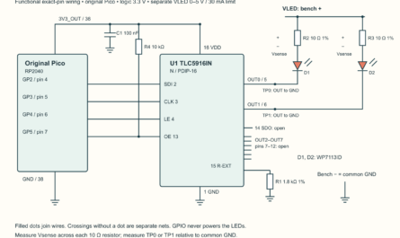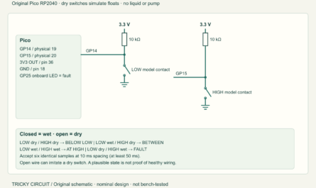
Binary equality is only one possible comparison. An electronic selector may need to know whether a requested value is below, equal to or above a limit. Build a four-bit magnitude comparator with eight switches and three indicators. Change the most significant bit and watch it outweigh every lower bit; then discover why the cascade inputs must be wired even when there is only one chip.
This exact-part circuit and its logical oracle are prepared for a low-voltage bench experiment. No physical assembly, waveform measurement or target firmware execution is claimed. The ordering map is calculated from valid settled input words; it is not an oscilloscope trace.
A number is more than a collection of lit bits
A magnitude comparator decides which of two numbers is larger. The Texas Instruments CD74HC85E compares two four-bit words, A and B, and provides three separate outputs: A less than B, A equal to B and A greater than B. A bit is a binary digit, zero or one. In this unsigned experiment, the four positions have weights 1, 2, 4 and 8. The most significant bit has the largest weight; a difference there settles the comparison regardless of the lower positions.
This is a digital comparison of encoded numbers, not an analog voltage comparator. Four HIGH inputs encode fifteen, rather than a measured 15 V. It is also not a subtractor: the outputs give a relation, not a numerical difference. The chip does not remember an old word or decide when moving switches constitute a completed update.
Cascade inputs carry the comparison result of a less significant section when several chips form a wider comparator. For a standalone section, the imaginary lower section is equal: set the equality input HIGH and the less/greater inputs LOW. When local A and B differ, their comparison decides the output; when they match, the lower-section result matters. These inputs are functional signals, not spare pins.
Exact hardware and physical connections
Use TI CD74HC85E, N package, a 16-pin plastic dual in-line package (PDIP); a regulated 4.5 V source with a 20 mA current limit; a 100 nF ceramic bypass; eight single-pole double-throw (SPDT) selectors; eight 1 kΩ series resistors; eight 10 kΩ pulldowns; and three red light-emitting diodes (LEDs), each with its own 3.3 kΩ resistor. Ω denotes ohm, kΩ one thousand ohms, nF nanofarad, V volt and mA milliampere. Use resistors rated at least 0.125 W.
| Group | Physical pins | Meaning |
|---|---|---|
| A0,A1,A2,A3 | 10,12,13,15 | Weights 1, 2, 4, 8 |
| B0,B1,B2,B3 | 9,11,14,1 | Weights 1, 2, 4, 8 |
| Lower less/equal/greater | 2,3,4 | Ground, +4.5 V, ground for standalone use |
| Greater/equal/less outputs | 5,6,7 | Separate active-HIGH indications |
| Supply and return | 16,8 | +4.5 V, ground; 100 nF directly between them |
Read the top-view notch and pin-one drawing before insertion. The exact HC device operates at 2–6 V; this experiment chooses 4.5 V so its published 4.5 V input limits apply. A valid HIGH is at least 3.15 V and a valid LOW at most 1.35 V. A voltage between these limits is undefined. The 7 V absolute supply boundary is a stress limit, not a working supply. CD74HCT85 is a different input-level variant; this is not a permission to substitute by similar name.
Build eight defined input cells
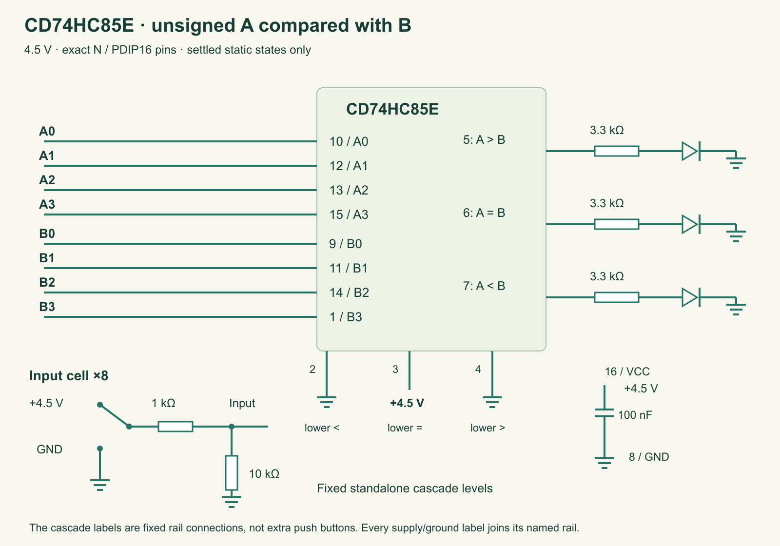
tricky-circuit-batch008-campaigns71-74/images/cd74hc85-magnitude.svg) · Full-size circuit.Disconnect power before wiring. Each selector chooses ground or +4.5 V; its common contact feeds the relevant input through 1 kΩ. Add 10 kΩ from the chip input to ground. This defines an open contact as LOW and limits accidental contact current. At HIGH, that cell forms a divider: 4.5 × 10/11 ≈ 4.09 V, above the required 3.15 V. Check real levels if the result is unexpected.
Each output feeds its own 3.3 kΩ resistor, then an LED anode; the cathode returns to ground. With an illustrative 1.6 V forward drop, its load is approximately (4.5 − 1.6)/3300 ≈ 0.88 mA. Brightness is not a voltage measurement; the forward drop varies. Do not join the three push-pull outputs together. A valid settled comparison normally asserts one result, but shorting outputs is not a way to combine their information.
Keep every input defined and keep the bypass close to the supply pins. Raw HC inputs need sufficiently fast transitions. Do not add a large capacitor to an input as a casual switch-debounce fix. This experiment records settled words after contact movement stops. A clocked receiving circuit and qualified conditioning are needed for a design that must capture a changing word at a defined instant.
Make significance and equality visible
- With all A and B selectors LOW, power the circuit and record the supply at pins 16 and 8. The equal output should be HIGH. Measure all three outputs, rather than judging only LED brightness.
- Keep B=7, written 0111. Set A=8, written 1000. The greater output should be HIGH even though B has more one bits. Magnitude depends on position, not the number of illuminated switches.
- Try A=7,B=8; A=15,B=15; A=0,B=15 and A=1,B=2. Predict each result before moving the selectors.
- For a fixed B, step A from 0 through 15. Record the one equal point and the regions below and above it. Repeat with another B and compare the map.
- Power off and inspect the three cascade inputs if equality never works. Do not deliberately float them during a live test. A wired standalone baseline is a controlled input condition.
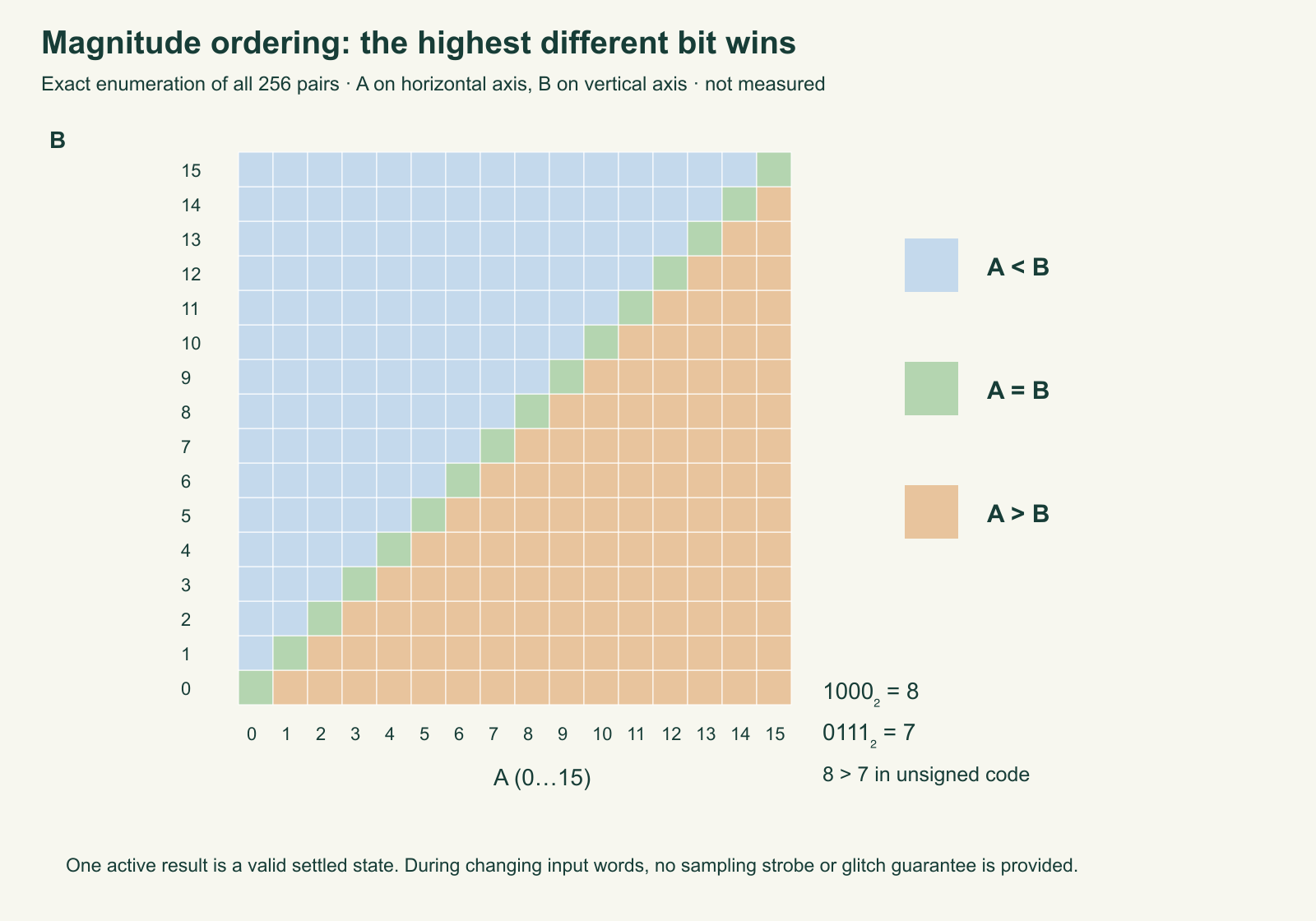
tricky-circuit-batch008-campaigns71-74/images/cd74hc85-magnitude-ordering.svg) · Full-size plot.Use the blank observation sheet (ZIP; file: tricky-circuit-batch008-campaigns71-74/code/cd74hc85-magnitude-observations-blank.csv). Sequentially moving four selectors passes through intermediate words. A briefly different output can be a legitimate comparison of one of those words, not a faulty arithmetic unit. Separately, internal path delays can produce short transient results. The static map does not promise that every output change is glitch-free.
Complete logical oracle and a wider-number example
The Python 3.11 program runs on a host computer and needs no microcontroller. It compares valid four-bit words and accepts a valid one-hot lower result: one of the three result signals is asserted. Unknown inputs return None; unsupported cascade combinations are rejected rather than presented as a model of illegal hardware states. The optional eight-bit function compares lower and upper nibbles, where a nibble is four bits. It demonstrates significance without claiming a second chip was wired.
"""CD74HC85E valid-state logical oracle; not a propagation/silicon model."""

def word(value, maximum=15):
    if type(value) is not int or not 0 <= value <= maximum:
        raise ValueError("word outside the declared unsigned range")
    return value


def compare4(a, b, lower=(0, 1, 0)):
    """Output tuple: (A<B, A=B, A>B). Only valid one-hot lower states modelled."""
    lower = tuple(lower)
    if len(lower) != 3 or any(type(x) is not int or x not in (0, 1) for x in lower):
        raise ValueError("lower state needs three integer bits")
    if sum(lower) != 1:
        raise ValueError("this oracle refuses unsupported cascade input combinations")
    if a is not None:
        word(a)
    if b is not None:
        word(b)
    if a is None or b is None:
        return None
    if a < b:
        return (1, 0, 0)
    if a > b:
        return (0, 0, 1)
    return lower


def compare8(a, b):
    word(a, 255); word(b, 255)
    low = compare4(a & 15, b & 15)
    return compare4(a >> 4, b >> 4, low)


if __name__ == "__main__":
    print("A,B,less,equal,greater")
    for a, b in [(0, 0), (7, 8), (8, 7), (15, 15), (1, 2)]:
        print(a, b, *compare4(a, b), sep=",")
Host checks execute all 256 four-bit comparisons and all 65,536 eight-bit comparisons, as cases within named behavior groups. They also test equal-section forwarding, unknowns, invalid values and unsigned interpretation. Those checks verify the supplied logic, not package continuity, output voltage or a physical propagation delay. The bench sheet intentionally contains no synthetic readings.
Diagnose a wrong relation
If a weight behaves backwards, inspect the A/B pin assignments: their physical order is not simply A0,A1,A2,A3 down one side. If equal is always off, verify cascade pin 3 is HIGH and pins 2/4 are LOW. If more than one LED appears on, measure settled output levels and inspect shorts or changing inputs before interpreting the display. A reversed LED can hide a correct output.
The chip interprets the bit pattern in the intended unsigned ordering. It does not know a program’s signed-number convention. An output relation also says nothing about whether the input came from an accurate sensor or a complete received message. Separate the encoding, update timing and comparison result in the experiment record.
Challenge: is 1000 a negative number?
In four-bit two’s-complement arithmetic, 1000 represents −8. Why does this circuit say 1000 is greater than 0111?
Answer
The circuit sees unsigned weights 8, 4, 2, 1, so it compares 8 with 7. Two’s complement is a signed encoding convention that changes the significance of the top bit. A signed comparator needs that convention handled explicitly; changing the label on a wire does not change this unsigned experiment.
Primary references
TI CD74HC85 SCHS136F, February 2022 supplies exact pins, cascade functions, operating levels and timing conditions. Current TI documentation was checked October 20, 2026; no separate applicable errata sheet surfaced, which is not proof of absence. The Python 3.11 documentation supports the host workflow. Continue with the electronics course.
Download the reader files (ZIP): the complete program, blank observation sheet and original editable SVG/PNG diagrams for cd74hc85-magnitude are inside tricky-circuit-batch008-campaigns71-74/. The inline program above is complete; the download is supplementary.