A digital potentiometer does not create an arbitrary ideal voltage. It moves a contact along a finite resistor string, has contact resistance, and supplies a load through that resistance. Use a Microchip MCP41010-I/P to compare commanded position with a real, loaded output. The interesting result is the curve between those two quantities.
This exact-part experiment and its complete program have not been physically assembled or run on the target board. Plots are calculated, using stated assumptions. Host fault checks exercise the supplied code; the observation sheet is blank.
A controlled attenuator, with a contact in the path
The MCP41010 is a single, volatile, eight-bit digital potentiometer. Volatile means its commanded position does not survive a supply interruption. Its resistance string has 256 sections and 256 available wiper codes, 0 through 255. The nominal end-to-end resistance is 10 kΩ, where Ω denotes ohm and kΩ one thousand ohms. A wiper is the movable electrical contact; it is not an ideal buffer amplifier.
We connect terminal A (PA0, physical pin 5) to 3.3 V, terminal B (PB0, physical pin 7) to ground, and measure the wiper W (PW0, physical pin 6). That arrangement is an attenuator: it selects a fraction of an existing voltage. It cannot generate a negative voltage or a voltage above its supply. Loading the wiper changes that fraction, so this is a useful lesson before treating a digitally selected voltage as a reference or a control signal.
Use the exact Microchip MCP41010-I/P, industrial-temperature plastic dual in-line package (PDIP), eight pins. The current manufacturer page lists it in production but recommends MCP4151-103 for new designs. This lesson deliberately examines the documented legacy part; the recommendation does not establish that another part accepts the same commands. The dual MCP42XXX family has different features and pins.
Parts and exact connections
Use an original Raspberry Pi Pico with MicroPython 1.26.0, the exact potentiometer, a 100 nF ceramic bypass capacitor, a 10 kΩ chip-select pullup, one removable 10 kΩ load and a voltmeter with known input resistance. nF means nanofarad, V volt and mA milliampere. Resistors rated 0.125 W or higher are sufficient here. The Universal Serial Bus (USB) connection powers the Pico; the integrated circuit and all its analog terminals use the Pico’s regulated 3.3 V rail.
| MCP41010 physical pin | Connection | Purpose |
|---|---|---|
| 1 CS | Pico GP17, physical 22; 10 kΩ to 3.3 V | Active-LOW chip select; idle HIGH |
| 2 SCK | GP18, physical 24 | Serial clock |
| 3 SI | GP19, physical 25 | Serial data input |
| 4 VSS,7 PB0 | Ground, Pico physical 23 | Digital return and lower terminal |
| 6 PW0 | Voltmeter positive; optional 10 kΩ load to ground | Wiper output |
| 5 PA0,8 VDD | 3.3 V, Pico physical 36 | Upper terminal and supply |
GP means general-purpose pin; the general-purpose input/output interface is abbreviated GPIO. Serial Peripheral Interface (SPI) sends clocked data to the chip. This single-potentiometer device has no serial data output, so there is no readback wire. The data connection is controller output to chip SI, commonly called master-out/slave-in (MOSI). Leave no imagined master-in/slave-out (MISO) connection on this eight-pin part.
Wire the resistor string, not an imaginary output amplifier
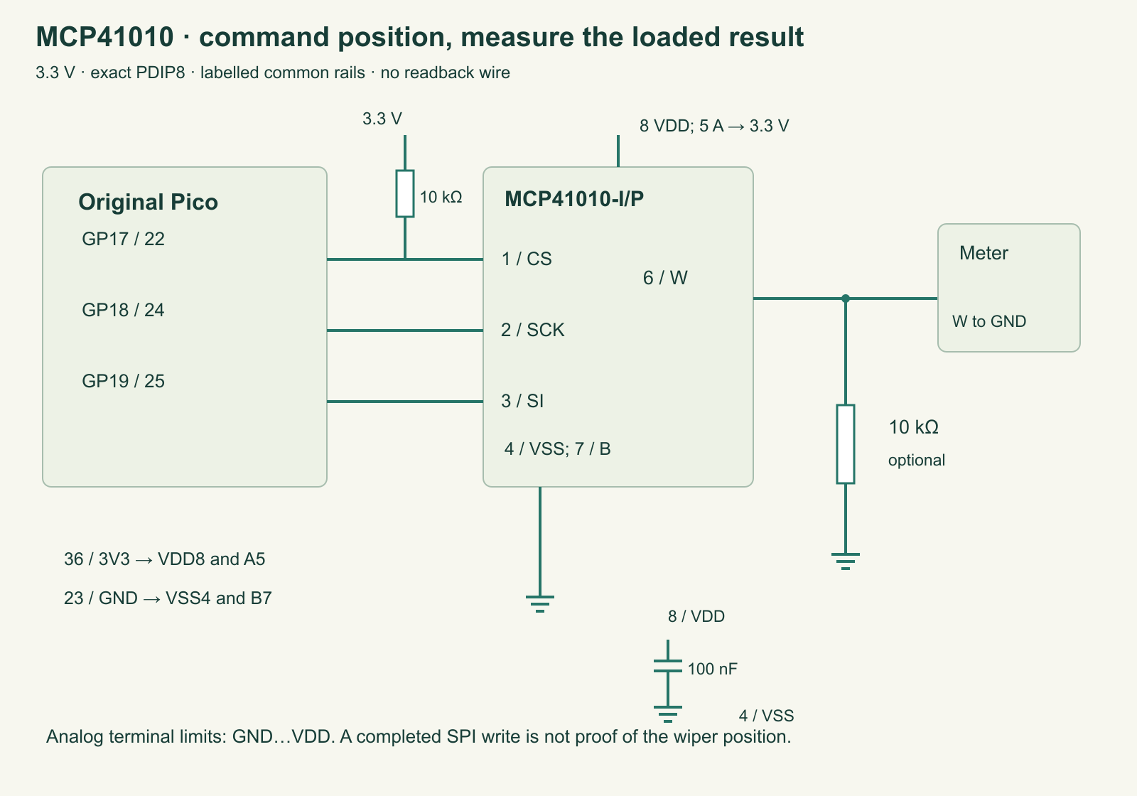
tricky-circuit-batch008-campaigns71-74/images/mcp41010-wiper-endpoints.svg) · Full-size circuit.Power off while wiring. Place 100 nF directly between pins 8 and 4 and keep the clock/data wires short. Check the package notch before applying power. Both the digital pins and every analog terminal must stay within their specified operating conditions; this is not a way to insert a 12 V signal into a 3.3 V control circuit. The manufacturer specifies 2.7–5.5 V operating supply. Choosing a common 3.3 V rail avoids an intentional logic-level mismatch.
The 10 kΩ end-to-end value is nominal: the datasheet gives 8–12 kΩ at its stated 25 °C test condition. At the minimum resistance, the entire string draws 3.3/8000 ≈ 0.413 mA. A 10 kΩ wiper load cannot draw more than 3.3/10000 = 0.33 mA in this fixture, below the specified ±1 mA wiper-current operating limit. Do not attach an LED, motor or low-resistance load directly and assume the wiper is a power output.
Calculate what the load does
For code D, the ideal unloaded fraction is D/256. Code 255 therefore stops one string section short of terminal A. Let RAB be the actual end-to-end resistance and RW the contact resistance. With A at VS and B at ground:
Rbottom = RAB × D/256; Rtop = RAB − RbottomVth = VS × D/256; Rth = (Rtop × Rbottom)/RAB + RWVout = Vth × RL/(RL + Rth)
This is a Thevenin equivalent: an ideal source Vth in series with Rth. RL is the total resistance from W to ground, including the meter in parallel with any added load. At midscale, nominal RAB = 10 kΩ and an assumed RW = 75 Ω give Rth = 2575 Ω. A 10 kΩ load then reduces an ideal 1.65 V to about 1.31 V. A 10 MΩ meter alone has a much smaller effect.
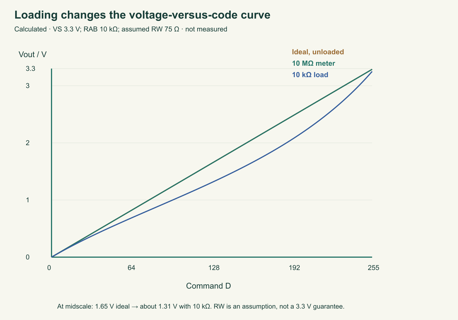
tricky-circuit-batch008-campaigns71-74/images/mcp41010-wiper-endpoints-loading.svg) · Full-size plot.The datasheet lists typical/maximal wiper resistance under particular supply and current conditions: 52/100 Ω at 5.5 V and 73/125 Ω at 2.7 V, tested at code 0 and 1 mA. Our 75 Ω at 3.3 V is an explicitly chosen illustrative assumption, not an interpolated guarantee. Real string tolerance, contact resistance, supply and meter loading belong in the uncertainty record.
Complete driver: a command is not a reading
The program uses SPI mode 0 at 100 kHz and sends a complete two-byte frame: command 0x11, then the validated code. It holds CS LOW for that frame and restores HIGH even when a write raises an exception. It clears the last-completed-command field before transmission; a partially failed transfer leaves the actual wiper position unknown. A successfully returned SPI write still does not prove that a chip was present or changed position.
"""MCP41010-I/P low-current attenuator, original Pico / MicroPython1.26.0.
Pure divider calculation also runs on a host. No command readback exists here.
"""
import math


def setting(code):
    if type(code) is not int or not 0 <= code <= 255:
        raise ValueError("code must be an integer from 0 to 255")
    return code


def loaded_voltage(code, supply=3.3, rab=10000.0, rw=75.0, load=10000.0):
    setting(code)
    for name, value in (("supply", supply), ("rab", rab), ("rw", rw), ("load", load)):
        if isinstance(value, bool) or not isinstance(value, (int, float)):
            raise ValueError(name + " must be numeric")
        if not math.isfinite(value) or value <= 0:
            raise ValueError(name + " must be finite and positive")
    bottom = rab * code / 256
    top = rab - bottom
    vth = supply * code / 256
    rth = top * bottom / rab + rw
    vout = vth * load / (load + rth)
    return {"assumed_vout": vout, "assumed_wiper_current": vout / load,
            "thevenin_ohms": rth, "model_only": True}


class MCP41010:
    def __init__(self, spi, cs):
        self.spi, self.cs = spi, cs
        self.last_completed_command = None
        cs.value(1)

    def set(self, code):
        setting(code)
        self.last_completed_command = None
        try:
            self.cs.value(0)
            self.spi.write(bytes((0x11, code)))
        finally:
            self.cs.value(1)
        # A completed software frame is NOT proof of resistor state or connection.
        self.last_completed_command = code
        return {"command": code, "state": "COMMAND_ONLY", "readback": False}


def main():
    from machine import SPI, Pin
    from time import sleep_ms
    cs = Pin(17, Pin.OUT, value=1)
    spi = None
    try:
        spi = SPI(0, baudrate=100000, polarity=0, phase=0, bits=8,
                  firstbit=SPI.MSB, sck=Pin(18), mosi=Pin(19))
        pot = MCP41010(spi, cs)
        for code in (0, 1, 64, 128, 192, 254, 255, 128):
            print(pot.set(code))
            sleep_ms(1000)
    finally:
        cs.value(1)
        if spi is not None:
            spi.deinit()
        # Last resistance remains; deinitialising SPI does not reset the wiper.


if __name__ == "__main__":
    main()
The normal sequence visits 0,1,64,128,192,254,255 and 128 with one-second dwell times. Cleanup releases CS and deinitializes the bus. Deinitializing SPI does not reset the potentiometer or force a safe analog output. Power-on reset selects midscale, but a script restart without a supply interruption is not power-on reset. Confirm W with the meter before connecting any later circuit.
Measure endpoints and loading separately
- Start with no extra wiper load. Record part marking, supply and meter input resistance in the blank worksheet (ZIP; file:
tricky-circuit-batch008-campaigns71-74/code/mcp41010-wiper-endpoints-observations-blank.csv). - Run the sequence and record W for each completed command. Compare D/256 against the measured ratio W/VS; do not silently force code 255 to mean 100%.
- Power off, add the 10 kΩ load and repeat. Look particularly at midscale. Account for the meter in parallel with the added load.
- Compare measurements with the model using the real measured RAB when available. Keep assumed RW visibly marked as assumed.
- If a command raises an exception, stop interpreting its position as known. Inspect wiring, restore a deliberate command and verify W. Never use a host mock failure as proof of behavior on a broken physical bus.
Host checks execute every command frame, reject bad values before bus activity, inject transfer failures and verify CS cleanup. They exercise all 256 model codes, endpoint behavior, monotonic loading and the current budget. They cannot measure analog accuracy, contact noise or resistance after a real fault.
Why is the last position below the rail?
A meter reports slightly less than the upper rail at code 255. Must the part be defective?
Answer
No. The ideal code fraction is 255/256, not 255/255, and the wiper has contact resistance. Loading can reduce it further. Compare the result with the exact device’s specified behavior and actual fixture conditions before concluding there is a fault.
Primary sources
Microchip DS11195C defines the exact pins, command framing, resistor string, reset state and electrical limits. The current MCP41010 product page was checked October 20, 2026, including its newer-part recommendation; no separate applicable errata surfaced, which is not proof of absence. MicroPython 1.26 SPI and the original Pico datasheet support the adapter. Continue with the electronics course.
Download the reader files (ZIP): the complete program, blank observation sheet and original editable SVG/PNG diagrams for mcp41010-wiper-endpoints are inside tricky-circuit-batch008-campaigns71-74/. The inline program above is complete; the download is supplementary.