A narrow view can exclude the edge of a shelf. It can also exclude useful reflected light. This experiment changes the receiving area of a VL53L1X distance sensor, then asks two separate questions: did a new result arrive, and is that result acceptable? A smaller number on the display is not an answer to either question.
Time of flight (ToF) means estimating distance from the travel time of emitted and returned light. A region of interest (ROI) selects part of the receiving detector array. Field of view (FoV) describes the angular region the sensor can observe. Here we compare centered 16 × 16, 8 × 8 and 4 × 4 regions, then return to 16 × 16 as a drift check. We keep the target still while changing one setting.
This is a finite educational comparison, not a collision detector, calibrated ruler or safety supervisor. The programs have host tests; no Arduino firmware build, target execution or physical distance results are claimed. The original drawings show intended connections and constructed timing, not a tested assembly.
Use the specified carrier and library
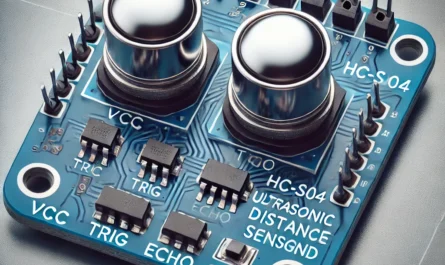
Use an original Arduino UNO Rev3 with its ATmega328P microcontroller at 16 megahertz (MHz), Pololu carrier #3415, four short jumper wires, a Universal Serial Bus (USB) cable, a ruler and a large matte target. Use Arduino AVR Boards core 1.8.6 and Pololu’s VL53L1X library 1.3.1. AVR names the microcontroller architecture; the board core supplies its input/output and timing support. A library is reusable code, not proof that every bus operation or physical reading succeeded.
Pololu identifies #3415 as carrying ST VL53L1CXV0FY/1. ST describes the module package as an optical land grid array with twelve terminals (Optical LGA12). This lesson connects the carrier’s header, not those tiny module lands. Several different Pololu distance carriers share a similar circuit-board outline; a board that looks right is not sufficient identification. Record the seller, board identity and visible sensor marking before powering it.
The reviewed ST datasheet is DS12385 revision 8, August 2024. Its recommended module supply is 2.6–3.5 volts (V), with 2.8 V nominal; those are bare-module values. The carrier adds a 2.8 V regulator and bus level shifting, so its VIN power input accepts a wider range. Our fixture uses the UNO’s 5 V rail, comfortably inside Pololu’s specified carrier range. Never apply that 5 V directly to a bare module’s supply or unshifted signal. Absolute maximum ratings are damage limits, not operating targets.
Pololu gives typical active current near 20 milliamperes (mA), with peaks up to about 40 mA depending on configuration. Supply the carrier from the board’s power terminal, never from an ordinary signal output. Use one USB source for the UNO and its attached carrier. Do not add an external positive supply or feed the carrier’s regulated output back into another power rail.
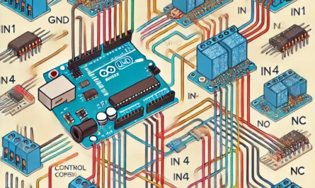
Trace the four complete connections
Disconnect USB before wiring. Ground (GND) is the common voltage reference and current return. The Inter-Integrated Circuit (I²C) bus has serial data (SDA) and serial clock (SCL). Its open-drain drivers pull a line LOW or release it; pull-up resistors provide HIGH. The sketch uses the seven-bit address 0x29 at 100 kilohertz (kHz). ST’s 0x52 includes the write-direction bit and is not the address to pass to Arduino Wire.
| UNO Rev3 terminal | Pololu #3415 terminal | Purpose |
|---|---|---|
| 5V power | VIN, JP1 pin 2 | Carrier power input |
| GND | GND, JP1 pin 3 | Common return |
| A4 / SDA | SDA, JP1 pin 4 | Bidirectional data, shifted by carrier |
| A5 / SCL | SCL, JP1 pin 5 | Clock, shifted by carrier |
The separate SDA/SCL labels near AREF, the analog reference terminal, on the UNO Rev3 connect to the same bus as A4/A5; use one pair, not two sets of parallel wires. The header numbers above come from Pololu’s schematic. Match the printed terminal labels on the actual board; the illustration’s spacing is functional, not a mechanical drilling template.
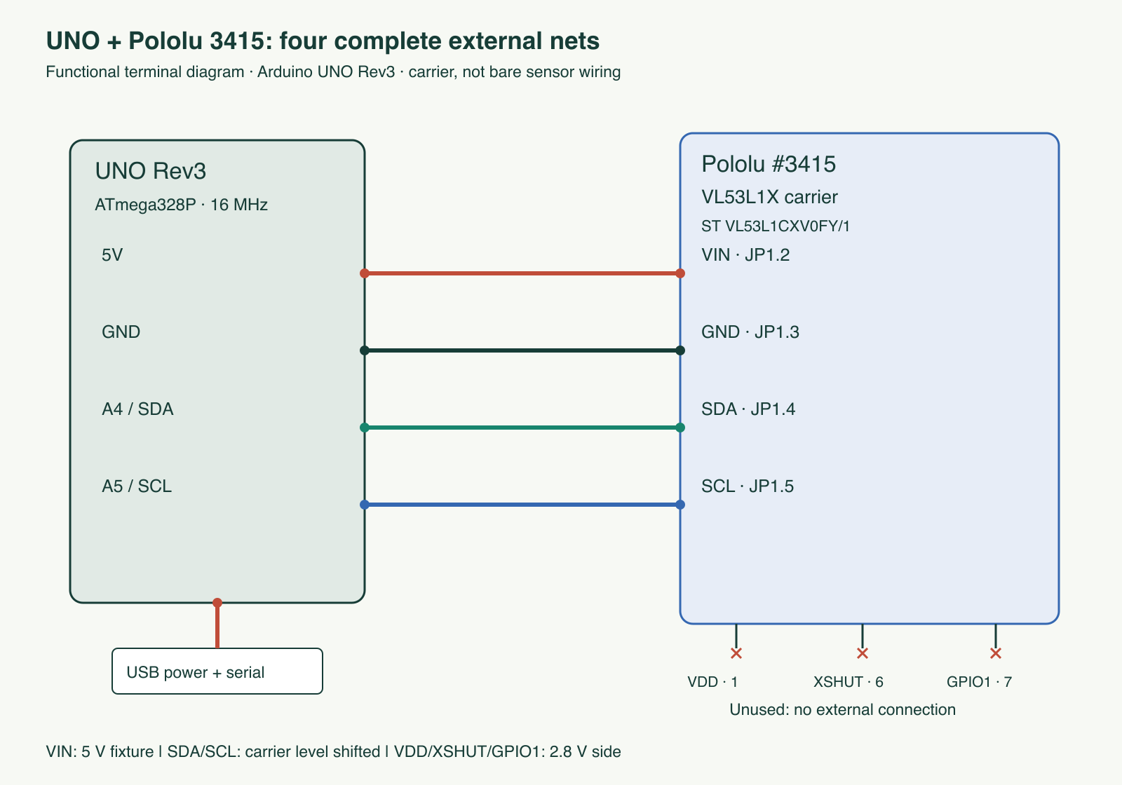
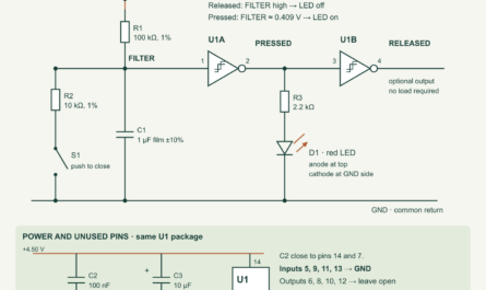
tricky-circuit-campaigns87-92/batch-009/images/uno-vl53l1x-roi-quality.svg) · Full-size Portable Network Graphics (PNG).Leave VDD, JP1 pin 1, unused: it is the regulator’s output. Leave XSHUT, pin 6, and GPIO1, pin 7, unconnected. General-purpose input/output (GPIO) means a configurable digital signal terminal. XSHUT is an active-LOW shutdown input; the carrier already pulls it up. GPIO1 is the interrupt output. These two signals are on the unshifted sensor-voltage side and are not 5 V tolerant. Do not attach UNO outputs to them in this experiment.
The reviewed carrier schematic already includes two 10 kilohm (kΩ) pull-ups toward VIN, two 10 kΩ pull-ups toward VDD, a dual-transistor level shifter, 47 kΩ pull-ups for the unshifted control signals, and 1 kΩ series resistors on their header paths. Its local supply capacitors are 1 microfarad (µF) and 0.1 µF on VIN, plus 1 µF, 4.7 µF and 0.1 µF on VDD. They support local current demand and reduce supply disturbance. Do not add a second set of bus pull-ups for this short single-carrier fixture.
Nominal pull-up contributions while a bus line is LOW:
5.0 V / 10 kΩ = 0.50 mA on the VIN side
2.8 V / 10 kΩ = 0.28 mA on the sensor side
Their sum is about 0.78 mA per LOW line, before other board pull-ups.
Those are nominal resistor calculations, not measured bus current or a complete rise-time analysis. The UNO core can enable its weak pull-ups as well. Long wires and added carriers change capacitance and loading; keep wires short, inspect HIGH/LOW levels when possible, and stop if communication is unreliable. At the module itself, pins 1 and 11 are supplies; 2, 3, 4, 6 and 12 are ground; 5 is XSHUT; 7 is GPIO1; 9 is SDA; 10 is SCL; and pin 8 is do-not-connect and must float. The carrier implements that internal wiring; do not solder extra jumpers to the module.
Fewer detectors do not mean more trustworthy millimetres
A single-photon avalanche diode (SPAD) is a light-sensitive detector capable of responding to individual photons. The receiver has 16 × 16 detector positions. ST permits a minimum ROI of 4 × 4, with its complete rectangle inside the array. Center numbers follow a hardware-specific map; they are not ordinary horizontal coordinates. This program deliberately uses only center 199 and square sizes 16, 8 and 4. It does not offer arbitrary zone positioning.
The selected areas are 256, 64 and 16 detector positions, a ratio of 16:4:1. That is a geometric count, not a guaranteed ratio of received signal, maximum range, precision or viewing angle. The datasheet gives a typical full diagonal view near 27° and programmable reduction toward 15°; do not calculate a 4 × 4 angle by multiplying 27° by 4/16. Detector response, optics, target coverage and processing remain involved.
A smaller region can exclude an off-axis object, but may also lose enough return light to fail the sensor’s checks. A single reported range is not a list of all targets and is not a guarantee that the nearest target was selected. This is a sequential single-zone comparison, not a simultaneous multizone depth camera.
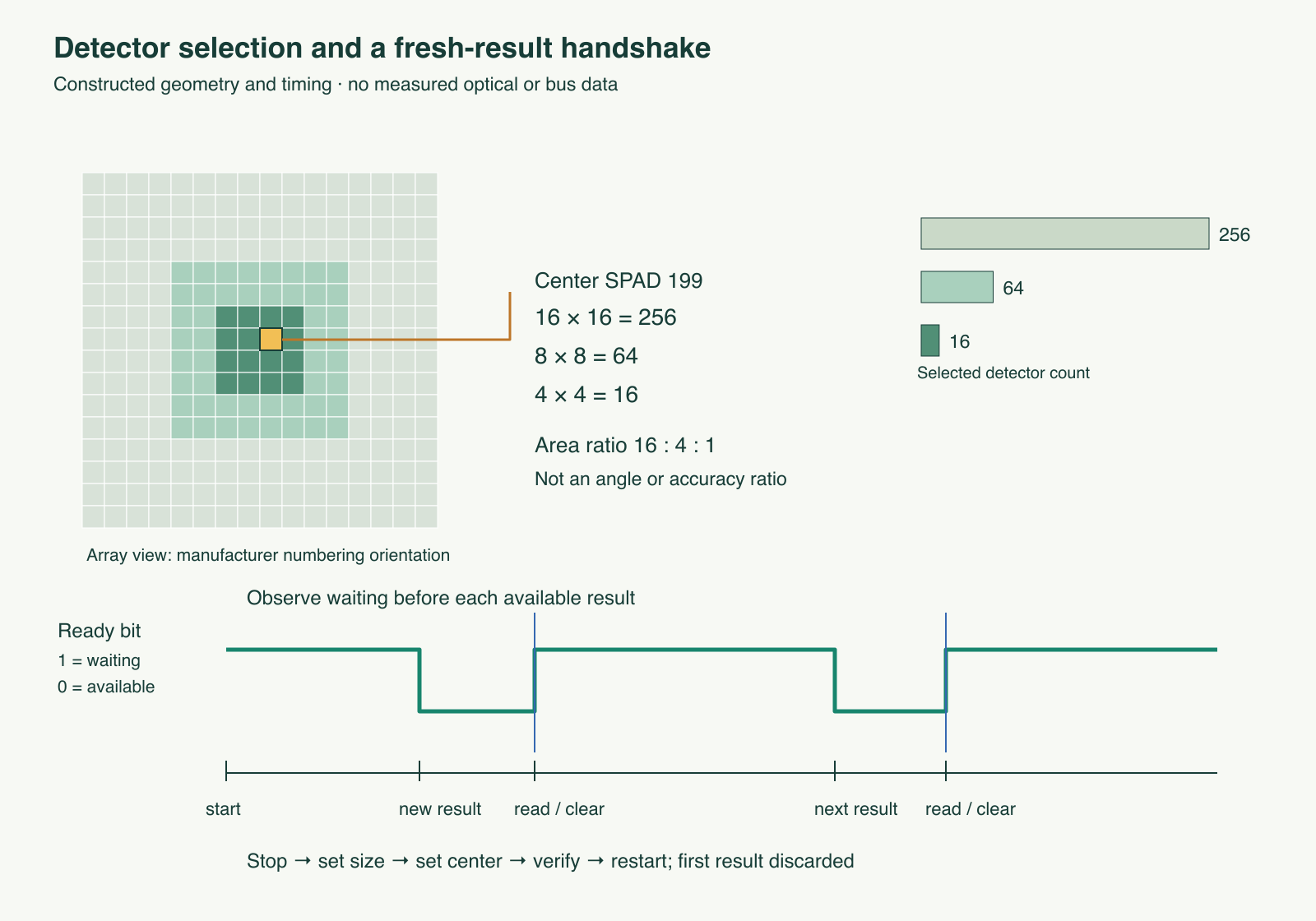
tricky-circuit-campaigns87-92/batch-009/images/uno-vl53l1x-roi-quality-logic.svg) · Full-size PNG.We request Short distance mode, a 50,000 microsecond (µs) timing budget and a 100 millisecond (ms) start-to-start intermeasurement period. One thousand microseconds make a millisecond. The budget allocates ranging work; the period spaces measurement starts. Neither is a host timestamp. Nominal 100 ms spacing corresponds to at most ten scheduled starts per second, before host overhead and faults. The 40–1200 millimetre (mm) acceptance interval is our conservative tabletop scope, not a new device specification.
Keep status, signal and freshness separate
The code reports Pololu 1.3.1’s mapped range-status numbers, not ST raw-register values or another driver’s status table. Only mapped RangeValid = 0 plus 40–1200 mm produces a distance field. A plausible number with SignalFail = 2 is withheld. Mapped 6 means a valid-range/no-wrap-check condition, often relevant to startup; it is also withheld. Mapped 13 indicates a rejected ROI/range condition. Never replace an invalid number with the previous good distance.
Signal and ambient rates use millions of counts per second (MCPS). They describe the sensor’s reported optical return and ambient contribution, not reflectance percentages. The sketch keeps both as diagnostics. It uses the same fixed-point conversion and integer distance correction as the pinned library:
reported_mm = floor((raw_range × 2011 + 1024) / 2048)
rate_MCPS = raw_rate / 128
accept_distance = (mapped_status == 0) AND (40 ≤ reported_mm ≤ 1200)
This correction is library behavior, not calibration performed by this lesson. ST recommends offset calibration, and its ROI guidance calls for per-zone calibration for best accuracy. We do not run those procedures, add cover glass, or claim factory values remove all error. Returning to 16 × 16 can reveal a changed scene; it cannot separate every drift mechanism.
For each size the application stops ranging, clears the old interrupt, sets size then center, verifies ROI center/size and the two Short-mode laser timing-period registers, restarts and observes a waiting ready bit. It then waits for that bit to indicate an available result. Each group contains one discarded startup result and five recorded results. Before accepting a row, checked reads obtain the complete seventeen-byte result packet on both sides of the library’s read(false). Both packets must agree, the read span must stay below our 30 ms application limit, those same selected registers must still agree, and the ready indication must have cleared. Consecutive stream values within one group must differ.
These checks bind a row to a host-observed handshake under normal device operation; they do not create a hardware measurement timestamp, a lossless frame counter or an atomic read guarantee from a protocol that lacks a checksum. Stream values are only compared for equality, not interpreted as an exact count of missing frames. An unnoticed sensor reset, other software sharing the bus, corruption that yields self-consistent bytes, or a pause spanning a complete host clock wrap can defeat the assumptions. Give this sketch exclusive sensor ownership.
Complete finite sketch and its fault boundary
The Wire application programming interface (API) supplies I²C transactions. Core 1.8.6’s 25,000 µs Wire timeout bounds its ordinary wait paths; the library’s timeout is separately set to 200 ms. Our checked reads require exact byte counts and acknowledgements. The ready loop also has a 300 ms deadline and 350-poll ceiling, so an ordinary frozen clock cannot create an infinite ready wait.
The unmodified library has an important limitation: last_status covers only its latest transaction, and its own reads do not validate every returned byte count. A later successful write can hide an earlier failed operation. The surrounding checked packets and selected register readbacks catch specific inconsistencies; they do not turn the library into a complete transaction audit. A passing run still needs electrical and optical qualification. This explicit boundary matters more than a reassuring “sensor connected” banner.
A bus timeout, short checked read, changed packet/configuration, duplicated stream or missed deadline latches the first fault and ends acquisition. Optical invalidity instead produces a WITHHELD row with an empty distance field. The stop path runs even after a fault, uses the library’s restoration sequence and independently repeats its stop command with acknowledgement checking. Failure to confirm that command prints STOP_UNCONFIRMED_REMOVE_USB. Disconnect power and inspect the cause; do not automatically resume. Even an acknowledged stop is not proof that the carrier is unpowered or its emitter physically disabled.
Save the sketch in a folder named uno-vl53l1x-roi-quality containing uno-vl53l1x-roi-quality.ino. In the Arduino Integrated Development Environment (IDE), select UNO and the stated board core and library versions, verify/build, inspect the actual flash and static random-access memory (SRAM) report, then upload. No invented size or successful AVR build is supplied here. Open Serial Monitor at 115200 bits per second; opening it normally resets this UNO and begins one finite run. Keep the complete output, including the final SESSION line.
Download the complete sketch (ZIP; file: tricky-circuit-campaigns87-92/batch-009/code/uno-vl53l1x-roi-quality.ino) · Blank comma-separated values (CSV) worksheet (ZIP; file: tricky-circuit-campaigns87-92/batch-009/code/uno-vl53l1x-roi-quality-observations-blank.csv).
// UNO Rev3; Arduino AVR Boards 1.8.6; Pololu VL53L1X 1.3.1.
// Finite centered-ROI experiment, not a calibrated or safety instrument.
#ifdef ROI_HOST_TEST
#include "roi-test-hal.h"
#else
#include <Arduino.h>
#include <Wire.h>
#include <VL53L1X.h>
#endif
#include <stdint.h>
#include <string.h>
#include <math.h>

class RoiExperiment {
 public:
  VL53L1X sensor;
  const char *fault = 0;
  uint8_t side = 16, previousStream = 0;
  bool haveStream = false;
  static const uint8_t ADDRESS = 0x29;

  bool fail(const char *reason) {
    if (!fault) fault = reason; // First uncertainty stays terminal.
    return false;
  }
  bool wireOK() {
    if (Wire.getWireTimeoutFlag()) return fail("WIRE_TIMEOUT");
    return !fault;
  }
  bool libraryOK() {
    // last_status is ONLY the last transaction, not an aggregate ACK log.
    bool timedOut = sensor.timeoutOccurred();
    if (sensor.last_status || timedOut) return fail("LIBRARY_IO");
    return wireOK();
  }
  bool burst(uint16_t reg, uint8_t *out, uint8_t n) {
    if (fault || !n || n > 17) return false;
    Wire.beginTransmission(ADDRESS);
    if (Wire.write(uint8_t(reg >> 8)) != 1 ||
        Wire.write(uint8_t(reg)) != 1) return fail("POINTER_WRITE");
    if (Wire.endTransmission(false) != 0) return fail("POINTER_NACK");
    uint8_t got = Wire.requestFrom(ADDRESS, n);
    if (got != n || Wire.available() != n) return fail("SHORT_READ");
    for (uint8_t i = 0; i < n; ++i) {
      int v = Wire.read();
      if (v < 0) return fail("EMPTY_READ");
      out[i] = uint8_t(v);
    }
    return wireOK();
  }
  bool writeByte(uint16_t reg, uint8_t v) {
    if (fault) return false;
    Wire.beginTransmission(ADDRESS);
    if (Wire.write(uint8_t(reg >> 8)) != 1 ||
        Wire.write(uint8_t(reg)) != 1 || Wire.write(v) != 1)
      return fail("REGISTER_WRITE");
    if (Wire.endTransmission() != 0) return fail("WRITE_NACK");
    return wireOK();
  }
  bool inactive() {
    uint8_t value;
    return burst(0x0031, &value, 1) &&
           ((value & 1) ? true : fail("READY_NOT_CLEARED"));
  }
  bool configuration() {
    uint8_t roi[2], a, b;
    if (!burst(0x007F, roi, 2) || !burst(0x0060, &a, 1) ||
        !burst(0x0063, &b, 1)) return false;
    uint8_t expected = uint8_t(((side - 1) << 4) | (side - 1));
    return (roi[0] == 199 && roi[1] == expected && a == 7 && b == 5)
        ? true : fail("CONFIG_CHANGED");
  }
  bool configure(uint8_t requested) {
    if (fault) return false;
    if (requested != 4 && requested != 8 && requested != 16)
      return fail("ROI_NOT_IN_EXPERIMENT");
    side = requested;
    sensor.stopContinuous();
    if (!libraryOK() || !writeByte(0x0086, 1) || !inactive()) return false;
    sensor.setROISize(side, side);
    if (!libraryOK()) return false;
    sensor.setROICenter(199); // After size: full-size setter can overwrite it.
    if (!libraryOK() || !configuration()) return false;
    haveStream = false;
    sensor.startContinuous(100); // Milliseconds, not the 50000 us timing budget.
    return libraryOK() && inactive();
  }
  bool waitReady() {
    uint32_t start = millis();
    // Finite poll count also stops a clock that no longer advances.
    for (uint16_t polls = 0; polls < 350; ++polls) {
      uint8_t value;
      if (!burst(0x0031, &value, 1)) return false;
      uint32_t age = uint32_t(millis() - start);
      if (age > 300) return fail("READY_DEADLINE");
      if (!(value & 1)) return true;
      delay(1);
    }
    return fail("POLL_BUDGET");
  }
  static uint16_t word(const uint8_t *p) {
    return uint16_t(uint16_t(p[0]) << 8) | p[1];
  }
  static uint16_t corrected(uint16_t raw) {
    return uint16_t((uint32_t(raw) * 2011UL + 1024UL) / 2048UL);
  }
  static uint8_t mappedStatus(uint8_t raw, uint8_t stream) {
    switch (raw) {
      case 17: case 2: case 1: case 3: return 5;
      case 13: return 13;
      case 18: return 10;
      case 5: return 4;
      case 4: return 2;
      case 6: return 1;
      case 7: return 7;
      case 12: return 9;
      case 8: return 3;
      case 9: return stream ? 0 : 6;
      default: return 255;
    }
  }
  static bool usable(uint8_t status, uint16_t mm) {
    return status == 0 && mm >= 40 && mm <= 1200;
  }
  bool sample(uint8_t sequence, bool discard) {
    if (fault || !waitReady() || !configuration()) return false;
    uint32_t start = millis();
    uint8_t before[17], after[17];
    if (!burst(0x0089, before, 17)) return false;
    uint16_t mm = sensor.read(false); // Calibration/DSS maintenance + IRQ clear.
    if (!libraryOK() || !burst(0x0089, after, 17)) return false;
    uint32_t span = uint32_t(millis() - start);
    if (span >= 30) return fail("READ_TOO_SLOW");
    if (memcmp(before, after, 17)) return fail("RESULT_CHANGED");
    if (!configuration() || !inactive()) return false;
    uint8_t stream = before[2];
    if (haveStream && stream == previousStream) return fail("DUPLICATE_STREAM");
    previousStream = stream;
    haveStream = true;
    uint8_t status = mappedStatus(before[0], stream);
    if (mm != corrected(word(before + 13)) ||
        uint8_t(sensor.ranging_data.range_status) != status ||
        sensor.ranging_data.peak_signal_count_rate_MCPS != word(before + 15) / 128.0f ||
        sensor.ranging_data.ambient_count_rate_MCPS != word(before + 7) / 128.0f)
      return fail("LIBRARY_RESULT_DISAGREES");
    Serial.print(side); Serial.print(','); Serial.print(sequence); Serial.print(',');
    Serial.print(discard ? F("DISCARD") : F("RECORD")); Serial.print(',');
    Serial.print(stream); Serial.print(','); Serial.print(status); Serial.print(',');
    Serial.print(!discard && usable(status, mm) ? F("VALID") : F("WITHHELD"));
    Serial.print(',');
    if (!discard && usable(status, mm)) Serial.print(mm);
    Serial.print(','); Serial.print(word(before + 15) / 128.0f, 3);
    Serial.print(','); Serial.print(word(before + 7) / 128.0f, 3);
    Serial.print(','); Serial.println(span);
    return true;
  }
  void stopBestEffort() {
    // No guard on fault: cleanup must still attempt the stop.
    sensor.stopContinuous();
    bool timedOut = sensor.timeoutOccurred();
    uint8_t lastStatus = sensor.last_status;
    // Repeat the stop command directly, since later library writes can mask NACK.
    Wire.beginTransmission(ADDRESS);
    bool complete = Wire.write(uint8_t(0x00)) == 1;
    complete = (Wire.write(uint8_t(0x87)) == 1) && complete;
    complete = (Wire.write(uint8_t(0x80)) == 1) && complete;
    uint8_t stopStatus = Wire.endTransmission();
    if (!complete || stopStatus || lastStatus || timedOut || Wire.getWireTimeoutFlag())
      { fail("STOP_UNCONFIRMED"); Serial.println(F("STOP_UNCONFIRMED_REMOVE_USB")); }
  }
  bool acquire() {
    const uint8_t regions[] = {16, 8, 4, 16};
    for (uint8_t r = 0; r < 4; ++r) {
      if (!configure(regions[r])) return false;
      for (uint8_t n = 0; n < 6; ++n)
        if (!sample(n, n == 0)) return false;
    }
    return true;
  }
  void run() {
    Serial.begin(115200);
    Wire.begin(); Wire.setClock(100000);
    Wire.setWireTimeout(25000, true); // Core 1.8.6 timeout, microseconds.
    Wire.clearWireTimeoutFlag();
    sensor.setTimeout(200); // Library timeout, milliseconds.
    bool initialized = sensor.init();
    if (!initialized) fail("INIT_FAILED");
    if (!libraryOK()) initialized = false;
    if (initialized) {
      if (!sensor.setDistanceMode(VL53L1X::Short)) fail("MODE_REJECTED");
      libraryOK();
      if (!fault && !sensor.setMeasurementTimingBudget(50000)) fail("BUDGET_REJECTED");
      libraryOK();
    }
    Serial.println(F("roi,sequence,phase,stream,pololu_status,quality,mm,signal_MCPS,ambient_MCPS,read_span_ms"));
    bool complete = !fault && acquire();
    stopBestEffort();
    if (!complete || fault) {
      Serial.print(F("SESSION_INVALID,")); Serial.println(fault ? fault : "UNKNOWN");
    } else Serial.println(F("SESSION_COMPLETE_NOT_CALIBRATED"));
  }
};
RoiExperiment experiment;
void setup() { experiment.run(); }
void loop() {} // Finite session. Restart manually after inspecting any fault.
The output has 24 result rows when every handshake succeeds: six per group, of which four startup rows are explicitly DISCARD. A later SESSION_INVALID means the overall session was not completed; keep that marker with any earlier rows. The empty loop() does not start another run. Inspect the setup before pressing Reset for a new trial.
A controlled target-and-ambient comparison
- With power disconnected, identify #3415, check all four terminal-to-terminal paths, and inspect for bridges. Remove the carrier’s protective shipping liner as Pololu directs. Do not dismantle the sensor, add focusing optics or point it deliberately at eyes. Retain the manufacturer’s unmodified optical assembly; its Class 1 classification is not a certification of a modified enclosure.
- Secure the carrier and a flat matte target 200–800 mm apart. Measure from a consistent sensor-face reference with the ruler and record its uncertainty. Keep the target larger than the observed region. A ruler comparison is a bench observation, not a traceable calibration.
- Upload the reviewed sketch, collect the complete 16→8→4→16 session, and copy each row with group identity to the blank worksheet. Record target material, position, ambient conditions, versions and power source. Preserve invalid rows and the discarded rows; do not average them into valid distances.
- Repeat without moving the fixture. Compare valid-row count, reported distances and signal/ambient diagnostics. Five recorded results per group are a small demonstration, not enough to establish an accuracy specification. Compare the first and last 16 × 16 groups for gross drift.
- Change one condition: replace a light target with a dark matte target at the same position, or change room illumination while keeping geometry fixed. Repeat the complete session. Do not assert that visible darkness predicts infrared reflectance.
- Place a second target partly toward an edge of the scene. Observe which configurations report valid ranges; do not conclude that any single result identifies every object or always chooses the nearest one. Return to the original scene before another comparison.
- For a recoverable communication fault trial, disconnect USB, remove SDA, then reconnect power. Expect a terminal failure rather than invented distance rows. Disconnect power again, restore the wire and restart manually. Do not unplug signal wires while powered or short them to test an error.
Keep laser/target geometry and environmental notes with every run. The code does not measure board temperature, actual optical field shape or the time a photon arrived. Persistent absence of a valid range is a result to investigate, not a reason to relax the status filter.
What has actually been checked
The delivered sketch was compiled for a host computer together with the unmodified, pinned Pololu 1.3.1 implementation and fake Arduino/Wire/time adapters. Twenty-four behavioral groups exercise its finite sequence, all 65,536 raw distance corrections, status gates, invalid ranges, short replies, negative acknowledgements (NACKs) and timeout paths, changed packets/configuration, duplicated streams, ready deadlines, frozen/wrapped clock cases and cleanup failure. These are executions of the actual delivered functions, not an Arduino firmware build, real I²C waveform or optical experiment.
Fresh manufacturer sources were checked for the carrier power and level shifting, module pinout/operating conditions, ROI geometry and calibration limitations. The current ST product documentation was checked for a separately listed errata sheet; none was identified in that reviewed list. That limited search does not prove that no limitation or later erratum exists. Inspect the current documents and actual carrier before hardware work.
The concepts behind the experiment are developed in the electronics course. For a different physical ranging mechanism, compare the ultrasonic distance lesson. Acoustic and optical target responses are different. This article’s practical question is the relation between detector selection, valid status and new-data evidence.
Challenge
The 16 × 16 group reports 503 mm with mapped status 0. The 4 × 4 group contains the raw-looking number 497 mm with mapped status 2. Which result is the more precise measurement?
Show the answer
The comparison does not establish precision for either setting. The 4 × 4 reading failed the signal check and must not be used as a distance; the sketch leaves that field empty. A valid 503 mm row is eligible for the limited comparison, but neither one row nor a narrower region establishes calibrated accuracy. Collect repeat trials, preserve status and environmental notes, and investigate the weak return.
Primary references
- Pololu #3415 product, exact sensor identity, connection and current guidance.
- Pololu carrier schematic, ©2016–2024: header and regulator/level-shifter networks.
- ST DS12385 revision 8, August 2024: module pins, operating limits and ranging/calibration behavior.
- ST UM2555 revision 3, December 2025: ROI center, complete-array bounds, timing and per-zone calibration. Its Ultra Lite Driver is a different API from the library used here.
- Pololu VL53L1X 1.3.1 source and MIT license: configuration, result correction, mapped status and transaction limitations.
- Arduino UNO Rev3 documentation and official terminal pinout.
- Arduino AVR Boards 1.8.6 Wire source: timeout and exact request/read interface.
- Current ST VL53L1X product documentation index.
Download the complete reader files (ZIP): full programs, blank observation worksheets, original editable SVG/PNG diagrams and selected support files for uno-vl53l1x-roi-quality. Inline main programs remain complete; this download is supplementary.