Materials Needed:
- Arduino (e.g., Arduino Uno)
- Relay Module (typically 5V)
- External Power Source (if needed for your load)
- Jumper Wires
- Load Device (e.g., a lamp or motor)
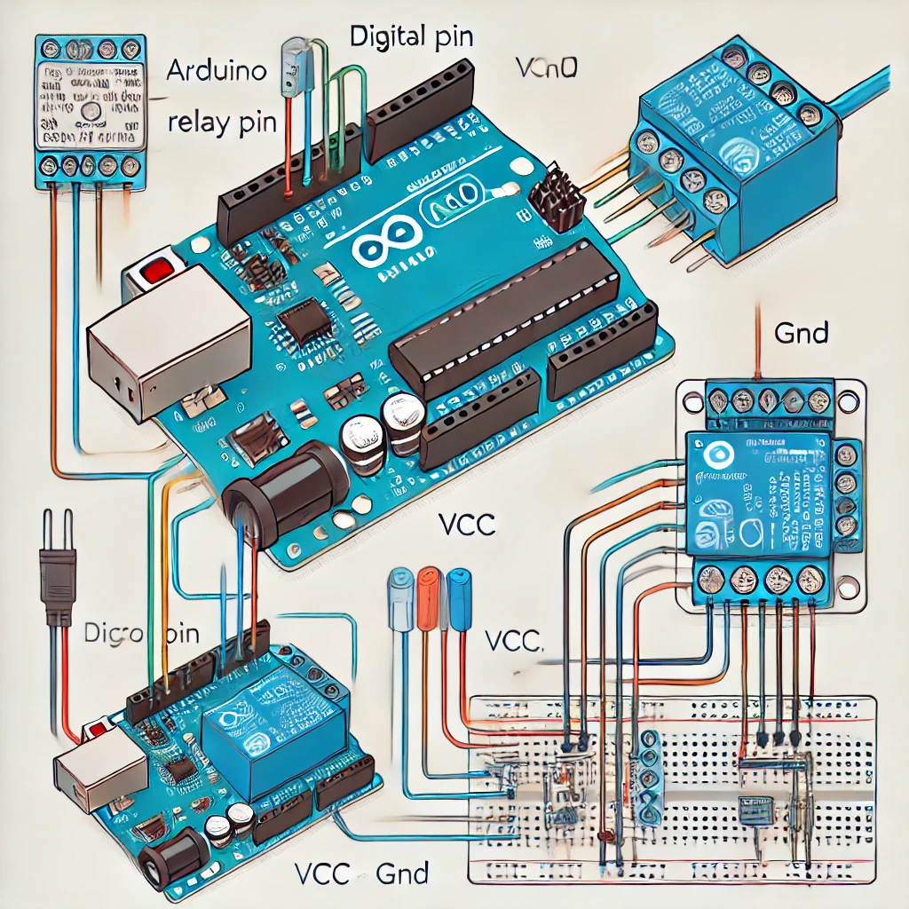
💡 Wiring Diagram:
- Relay Module to Arduino:
- VCC pin on the relay → 5V pin on Arduino (or 3.3V for 3.3V relays).
- GND pin on the relay → GND pin on Arduino.
- IN pin on the relay → Digital pin on Arduino (e.g., pin 7).
- Relay Contacts to Load:
- COM (Common) pin on the relay → Live wire (L) of the power source.
- NO (Normally Open) pin on the relay → One terminal of the load device (e.g., light bulb).
- The other terminal of the load device → Neutral wire (N) of the power source.
📟 Control Code:
int relayPin = 7;  // Pin connected to IN on the relay module

void setup() {
  pinMode(relayPin, OUTPUT);  // Set relay pin as output
}

void loop() {
  digitalWrite(relayPin, HIGH);  // Turn relay ON (close the switch)
  delay(1000);                    // Wait for 1 second
  digitalWrite(relayPin, LOW);   // Turn relay OFF (open the switch)
  delay(1000);                    // Wait for 1 second
}
⚠️ Important Notes:
- Ensure your load power source is appropriate (e.g., 120V AC for a lamp).
- Electromechanical relays may make a clicking sound when activated.
- High-voltage handling requires caution. Always be safe when working with AC circuits.