🔧 Components Needed
- Arduino (e.g., Uno)
- SG90 Servo Motor
- Potentiometer (e.g., 10kΩ)
- Two Push Buttons
- Jumper Wires & Breadboard
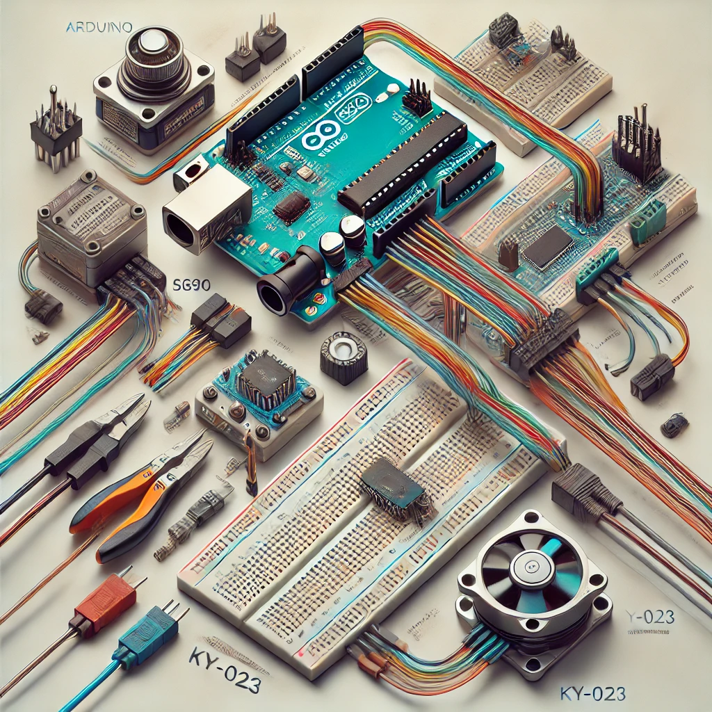
📌 Wiring Diagram
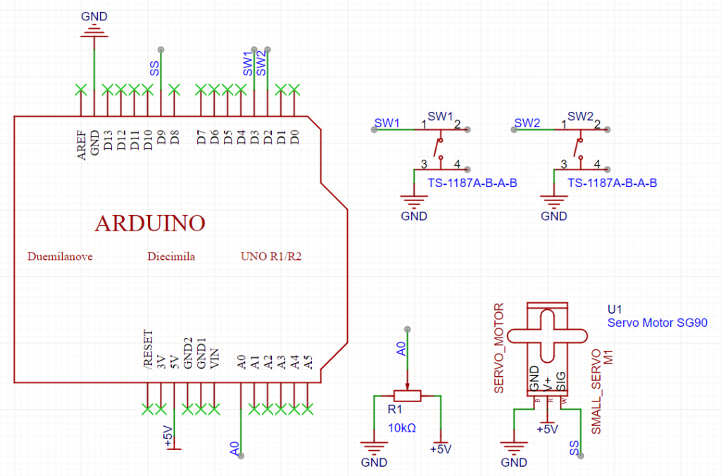
1. Servo Connection (SG90)
- VCC (Red): → Arduino 5V
- GND (Brown/Black): → Arduino GND
- Signal (Orange): → Digital Pin 9
2. Potentiometer Connection
- One Outer Pin: → Arduino 5V
- Other Outer Pin: → Arduino GND
- Middle Pin (Wiper): → Analog Pin A0
3. Button Connections
- Button 1 (Increase Angle):
- One terminal → Digital Pin 2
- Other terminal → GND
- Button 2 (Decrease Angle):
- One terminal → Digital Pin 3
- Other terminal → GND
Tip: Use the Arduino’s internal pull-up resistors for the buttons by setting their mode to INPUT_PULLUP.
💻 Example Code
Below is an example sketch that uses the potentiometer as a base angle and allows adjustment with two buttons:
#include <Servo.h>

Servo myServo;  // Create a servo object

// Pin Definitions
const int servoPin = 9;        // Servo signal pin
const int potPin = A0;         // Potentiometer analog input
const int buttonUpPin = 2;     // Button to increase angle
const int buttonDownPin = 3;   // Button to decrease angle

int servoAngle = 90;  // Starting at the middle position (90°)

void setup() {
  Serial.begin(9600);
  myServo.attach(servoPin);  // Attach the servo to the defined pin

  // Set pin modes for the potentiometer (default INPUT) and buttons
  pinMode(potPin, INPUT);
  pinMode(buttonUpPin, INPUT_PULLUP);    // Enable internal pull-up resistor
  pinMode(buttonDownPin, INPUT_PULLUP);

  myServo.write(servoAngle);  // Set initial servo position
}

void loop() {
  // 1️⃣ Read the potentiometer value and map it to a 0-180° range
  int potValue = analogRead(potPin);
  int mappedAngle = map(potValue, 0, 1023, 0, 180);

  // Use the potentiometer value as the base servo angle
  servoAngle = mappedAngle;

  // 2️⃣ If the "increase" button is pressed, add 90° to the angle
  if (digitalRead(buttonUpPin) == LOW) {
    servoAngle += 90;
    if (servoAngle > 180) servoAngle = 180;
    delay(200);  // Debounce delay
  }

  // 3️⃣ If the "decrease" button is pressed, subtract 90° from the angle
  if (digitalRead(buttonDownPin) == LOW) {
    servoAngle -= 90;
    if (servoAngle < 0) servoAngle = 0;
    delay(200);  // Debounce delay
  }

  // 4️⃣ Update the servo with the new angle
  myServo.write(servoAngle);

  // Debug: Print the current angle to the Serial Monitor
  Serial.print("Angle: ");
  Serial.println(servoAngle);

  delay(20);  // Small delay for smooth operation
}
📋 How It Works
- Potentiometer:
Reads an analog value (0–1023) and maps it to a servo angle (0°–180°). - Buttons:
- When the increase button is pressed, the angle increases by 90°.
- When the decrease button is pressed, the angle decreases by 90°.
(Internal pull-up resistors and a debounce delay help ensure reliable button presses.)
- Servo Control:
The servo’s position is continuously updated based on the potentiometer reading and button adjustments. - Serial Monitor:
The current servo angle is printed for debugging purposes.
🎯 Conclusion
This setup lets you control an SG90 servo using both a potentiometer (for smooth, continuous adjustment) and two buttons (for quick, incremental changes). It’s a great project for learning how to combine analog and digital inputs on the Arduino!
Enjoy your project! 😊👍