A relay is an electrically controlled switch that allows a low-power microcontroller (like Arduino, ESP32, Raspberry Pi, or STM32) to control high-power devices (motors, lights, heaters, etc.). 🚀
⚡ 1. Understanding Relay Modules
Types of Relays Used with Microcontrollers
✅ Electromechanical Relays (EMR) – Clicky, with physical contacts, handles AC/DC loads.
✅ Solid-State Relays (SSR) – No moving parts, faster switching, best for AC loads.
✅ Relay Modules (with built-in transistors & protection diodes) – Plug-and-play!
🔧 2. How to Connect a Relay to Microcontrollers
A microcontroller cannot drive a relay directly because it outputs low voltage (3.3V or 5V), while the relay coil may require higher current (70-150mA at 5V or 12V). Solution? Use a transistor!
🔹 Method 1: Connecting a Relay Module (Easy Way)
💡 If you have a ready-made relay module, it already has a transistor & diode built-in. Just connect it directly to your microcontroller.
🛠️ Wiring for a Relay Module
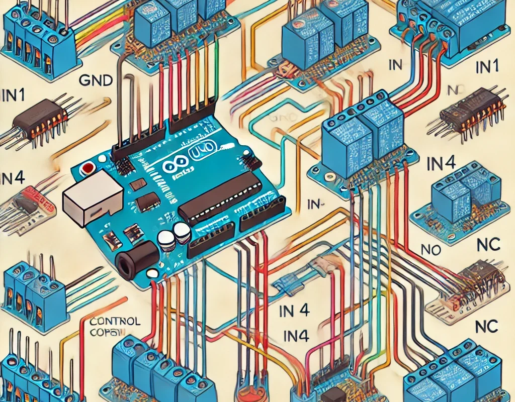
| Relay Pin | Connects To |
|---|---|
| VCC | 5V (or 3.3V for ESP32, if supported) |
| GND | GND of microcontroller |
| IN | Digital Pin (to control the relay) |
| COM (Common) | Connected to Load |
| NO (Normally Open) | Load’s live wire (default OFF) |
| NC (Normally Closed) | Load’s live wire (default ON) |
✅ When IN = HIGH, the relay turns ON (NO closes).
✅ When IN = LOW, the relay turns OFF (NO opens).
🔹 Method 2: Using a Transistor (For a Raw Relay)
If you have a bare relay, you’ll need a transistor (e.g., NPN 2N2222, BC547, TIP120) to switch it ON/OFF.
🛠️ Circuit Diagram
- Microcontroller GPIO → 1kΩ resistor → Transistor Base
- Transistor Collector → Relay Coil
- Transistor Emitter → GND
- Diode (1N4007) across the relay coil (for protection)
- Relay Common & NO/NC connected to the load
🤖 3. Connecting a Relay to Different Microcontrollers
🔹 Arduino (5V Logic)
✅ Directly connect IN to an Arduino digital pin.
✅ Works with 5V relay modules.
int relayPin = 7;
void setup() {
  pinMode(relayPin, OUTPUT);
}
void loop() {
  digitalWrite(relayPin, HIGH);  // Turns ON the relay
  delay(1000);
  digitalWrite(relayPin, LOW);   // Turns OFF the relay
  delay(1000);
}
🔹 ESP32 (3.3V Logic)
❌ Problem: Most relay modules require 5V signal, but ESP32 runs on 3.3V logic.
✅ Solution: Use a transistor circuit or a 3.3V relay module.
#define relayPin 2  // ESP32 GPIO2
void setup() {
  pinMode(relayPin, OUTPUT);
}
void loop() {
  digitalWrite(relayPin, HIGH);  // Relay ON
  delay(2000);
  digitalWrite(relayPin, LOW);   // Relay OFF
  delay(2000);
}
🔹 Raspberry Pi (3.3V Logic)
✅ Use a 3.3V relay module or an NPN transistor (like ESP32 setup).
import RPi.GPIO as GPIO
import time
relayPin = 17  # GPIO17
GPIO.setmode(GPIO.BCM)
GPIO.setup(relayPin, GPIO.OUT)
while True:
    GPIO.output(relayPin, GPIO.HIGH)  # Relay ON
    time.sleep(2)
    GPIO.output(relayPin, GPIO.LOW)   # Relay OFF
    time.sleep(2)
🔹 STM32 (3.3V Logic)
✅ Same as ESP32, use a transistor circuit if needed.
✅ Some STM32 boards have 5V pins, allowing direct connection.
⚠️ Safety Tips When Using Relays
⚡ Relays control HIGH VOLTAGE – Always be careful!
✅ Use optocouplers if controlling AC loads for isolation.
✅ Use a diode across the relay coil (if not using a module) to prevent voltage spikes.
✅ NEVER directly switch AC mains with a microcontroller – use relays rated for it.
🔥 Conclusion: Which Method is Best?
🔹 For Beginners → Use a relay module (easiest, no extra components needed).
🔹 For Low-Power Loads → Use a transistor to drive a relay coil.
🔹 For High-Voltage Loads → Use optocouplers & high-quality relays.