Arduino digital pins can be used for a variety of purposes, such as controlling LEDs, reading button states, driving motors, and communicating with sensors. Let’s go over how to use them effectively.
🔹 1. Overview of Arduino Digital Pins
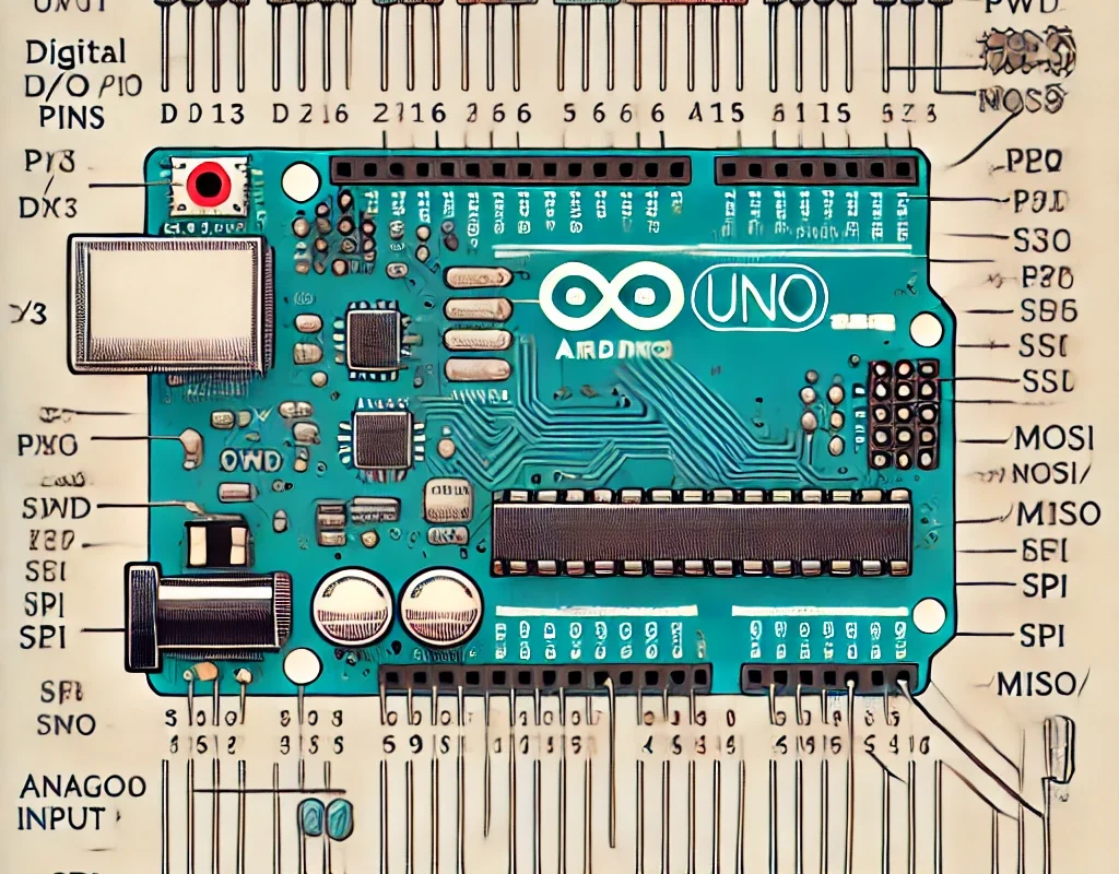
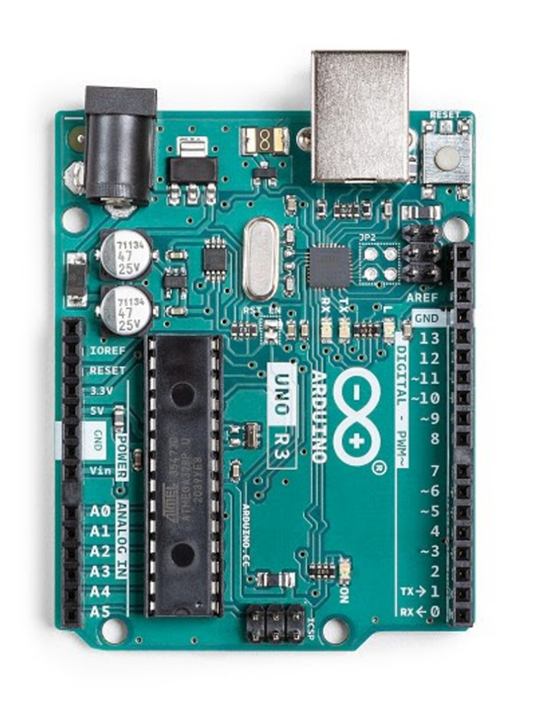
- Digital pins on Arduino Uno, Mega, Nano, and other boards are labeled D0 to D13.
- They can function as input or output using
pinMode(). - Can read/write only two states:
HIGH(5V or 3.3V on some boards).LOW(0V, ground).
- Some digital pins support PWM (Pulse-Width Modulation) for analog-like control.
📌 Example on Arduino Uno:
| Pin | Function |
|---|---|
| D0, D1 | UART TX/RX (Used for Serial Communication) |
| D2 – D13 | General Digital I/O Pins |
| D3, D5, D6, D9, D10, D11 | PWM Capable (~) |
| D2, D3, D18, D19, D20, D21 | External Interrupts |
🔹 2. Using Digital Pins as Outputs
Example: Controlling an LED
✅ Wiring:
| Arduino Pin | Component |
|---|---|
| D7 | LED Anode (+) |
| GND | LED Cathode (-) (through a 220Ω resistor) |
✅ Code:
void setup() {
    pinMode(7, OUTPUT); // Set pin 7 as an output
}

void loop() {
    digitalWrite(7, HIGH); // Turn ON LED
    delay(1000);           // Wait 1 second
    digitalWrite(7, LOW);  // Turn OFF LED
    delay(1000);           // Wait 1 second
}
📌 What happens?
- The LED blinks every second.
HIGH= LED ON,LOW= LED OFF.
🔹 3. Using Digital Pins as Inputs
Digital pins can be used to read button presses, sensor states, and logic signals.
Example: Reading a Button Press
✅ Wiring:
| Arduino Pin | Component |
|---|---|
| D2 | One side of the Button |
| GND | Other side of the Button |
📌 Use an internal pull-up resistor (INPUT_PULLUP) to keep the input stable.
✅ Code:
void setup() {
    pinMode(2, INPUT_PULLUP);  // Enable internal pull-up resistor
    pinMode(7, OUTPUT);        // LED as output
}

void loop() {
    if (digitalRead(2) == LOW) { // Button pressed
        digitalWrite(7, HIGH);
    } else {
        digitalWrite(7, LOW);
    }
}
📌 How it works?
- The button connects to GND when pressed.
- Pull-up resistor ensures the pin reads HIGH when not pressed.
🔹 4. Using Digital Pins for PWM (Analog Control)
PWM (Pulse-Width Modulation) allows simulating analog output using digital pins.
Example: Dimming an LED using PWM
✅ Wiring:
| Arduino Pin | Component |
|---|---|
| D9 (~PWM) | LED Anode (+) |
| GND | LED Cathode (-) (through a 220Ω resistor) |
✅ Code:
void setup() {
    pinMode(9, OUTPUT);
}

void loop() {
    for (int brightness = 0; brightness <= 255; brightness += 5) {
        analogWrite(9, brightness);
        delay(30);
    }
}
📌 What happens?
- The LED gradually brightens.
analogWrite(pin, value)takes values from 0 (off) to 255 (fully on).
🔹 5. Using Digital Pins for Serial Communication (TX/RX)
| Pin | Function |
|---|---|
| D0 (RX), D1 (TX) | UART Serial Communication |
📌 Example: Sending data to the Serial Monitor
void setup() {
    Serial.begin(9600); // Start serial at 9600 baud
}

void loop() {
    Serial.println("Hello, Arduino!");
    delay(1000);
}
📌 Warning: If using USB Serial (for programming), avoid using D0/D1 for other tasks.
🔹 6. Using Digital Pins for Interrupts
Interrupts allow immediate reaction to events (e.g., button press, sensor trigger).
| Pin | Interrupt Support (Uno) |
|---|---|
| D2, D3 | Yes (attachInterrupt) |
📌 Example: Button Interrupt
void handleInterrupt() {
    digitalWrite(7, !digitalRead(7)); // Toggle LED
}

void setup() {
    pinMode(7, OUTPUT);
    pinMode(2, INPUT_PULLUP);
    attachInterrupt(digitalPinToInterrupt(2), handleInterrupt, FALLING);
}

void loop() {
    // Nothing needed here, handled by interrupt
}
📌 Why use interrupts?
- Faster response than
loop(). - Runs immediately when triggered.
🔹 7. Using Digital Pins for I2C & SPI Communication
✅ I2C (For sensors, displays, etc.)
| Arduino Pin | I2C Function |
|---|---|
| A4 (SDA) | Data Line |
| A5 (SCL) | Clock Line |
📌 Example: Connect an I2C LCD Display
#include <Wire.h>
#include <LiquidCrystal_I2C.h>

LiquidCrystal_I2C lcd(0x27, 16, 2);

void setup() {
    lcd.begin();
    lcd.backlight();
    lcd.print("Hello, World!");
}

void loop() {}
✅ SPI (For SD cards, RFID, etc.)
| Arduino Pin | SPI Function |
|---|---|
| D10 | SS (Slave Select) |
| D11 | MOSI (Master Out, Slave In) |
| D12 | MISO (Master In, Slave Out) |
| D13 | SCK (Clock) |
📌 Example: SPI Communication (SD Card)
#include <SPI.h>
#include <SD.h>

void setup() {
    Serial.begin(9600);
    if (!SD.begin(10)) {
        Serial.println("SD Card failed!");
        return;
    }
    Serial.println("SD Card initialized.");
}

void loop() {}
📌 Use SPI for: SD cards, RFID, TFT displays.
🎯 Summary: What Can You Do with Digital Pins?
| Function | Pins Used | Example Use |
|---|---|---|
| Basic I/O | D2-D13 | Read buttons, control LEDs |
| PWM (Analog Output) | ~D3, ~D5, ~D6, ~D9, ~D10, ~D11 | Motor speed, LED brightness |
| Serial (UART) | D0, D1 | Debugging, ESP8266 communication |
| Interrupts | D2, D3 | Fast sensor response, button interrupts |
| I2C (Wire) | A4 (SDA), A5 (SCL) | LCD, sensors, EEPROM |
| SPI (Fast Communication) | D10-D13 | SD cards, RFID |
🚀 Conclusion
Arduino digital pins are highly versatile and can be used for basic I/O, PWM, serial communication, I2C/SPI interfaces, and interrupts. Whether controlling LEDs, reading sensors, or communicating with other devices, understanding digital pins unlocks the full potential of Arduino.