✅ Must-Have Components for Stable Operation
| Component | Purpose |
|---|
| ATtiny MCU | The brains of your project 🧠 |
| Power Supply (3.3V or 5V) | Stable voltage source from battery, regulator, or USB |
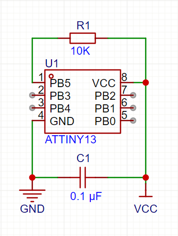
| 0.1 µF Ceramic Capacitor | Bypass capacitor between Vcc and GND for power noise filtering ⚡ |
| Reset Button (optional) | To manually reset the chip (only if RESET pin is active) |
| 10kΩ Pull-Up Resistor on RESET | Prevents false resets if RESET is not disabled via fuse bits |
| ISP Series Resistors (optional) | ~1kΩ protection when programming ATtiny in-circuit |
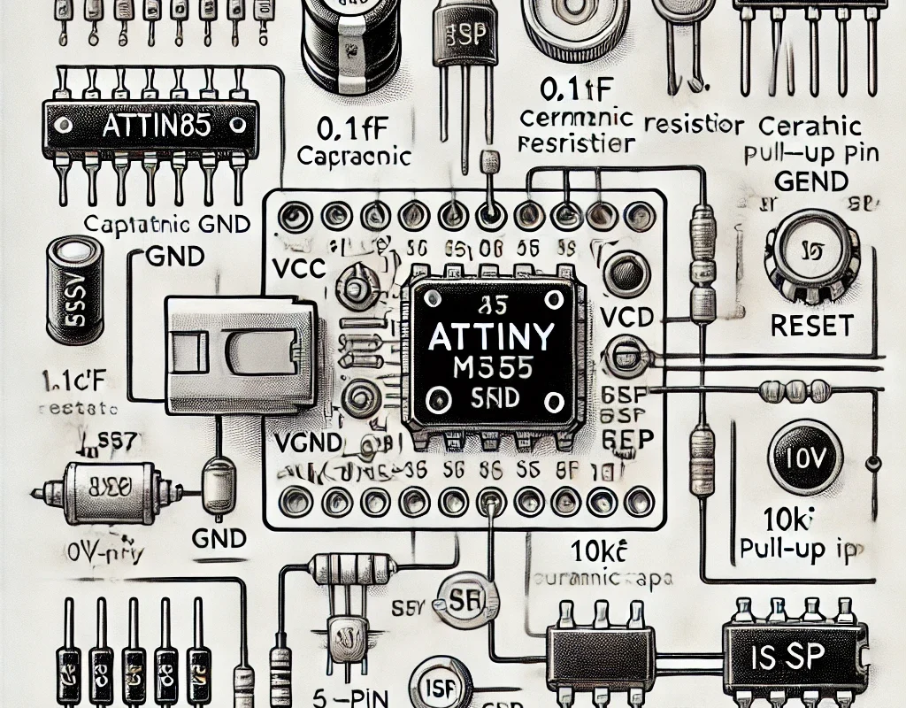
🧩 Basic Stable Circuit (ATtiny85 Example)
- Use
INPUT_PULLUP for buttons to avoid external resistors.
- Keep the power lines clean and tight!
🔋 Power Supply Options
| Power Source | Notes |
|---|
| CR2032 coin cell | For short-term portable use |
| Li-ion + LDO (AMS1117) | Stable 3.3V output, good for sensors & WiFi |
| USB 5V (via regulator) | Great for dev boards or breadboarding |
📦 Recommended Extras for Smooth Operation
| Component | Why It Helps |
|---|
| 10 µF Electrolytic Cap | Additional power smoothing, good for servos |
| Low ESR Ceramic Cap | Filters high-frequency noise |
| Perfboard or PCB | Avoids flaky connections from breadboards |
🛠️ Optional Peripherals — What to Add
| Peripheral | Add This |
|---|
| LEDs | 220–330Ω resistors on each pin |
| Buttons | Use INPUT_PULLUP or external 10kΩ resistor |
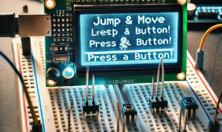
| OLED / LCD | Add 0.1µF and 10µF on Vcc near display |
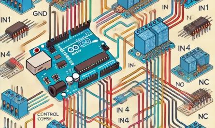
| Servos / Motors | Use separate power + decoupling caps |
📡Broadcast the signal — amplify the connection.