1️⃣ Concept Overview
- NE555 Timer in Astable Mode:
The NE555 can be configured in astable mode to produce a continuous square wave. By adjusting the RC (resistor-capacitor) network, you can set the oscillation frequency. - Frequency Sweep for Siren Effect:
To mimic a siren, the output frequency must gradually change (sweep) up and down. This can be achieved by modulating one or more of the timing resistors (often using a potentiometer or a modulation circuit). - Output to Speaker:
The square wave signal is used to drive a speaker or piezo buzzer. In many cases, you may want to include a coupling capacitor or a small amplifier to match the speaker’s impedance.
2️⃣ Components Needed
- NE555 Timer IC
- Resistors:
- Fixed resistor(s) for timing (e.g., R1)
- A variable resistor (potentiometer) for modulation (e.g., R2)
- Capacitor:
- Determines the basic oscillation frequency along with the resistors.
- Diodes (optional):
- Can help create separate charge and discharge paths for smoother frequency modulation.
- Speaker or Piezo Buzzer:
- For audio output (consider using an amplifier or a resistor if necessary).
- Breadboard and Jumper Wires
- Power Supply:
- Typically 5V (from a battery or regulated power source)
3️⃣ Circuit Design
🔌 Wiring Diagram
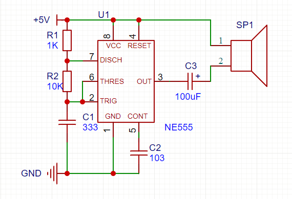
- R1 & R2:
- R1 is a fixed resistor, and R2 can be a potentiometer or a resistor network that you vary to create the sweep effect.
- C1:
- The capacitor, together with R1 and R2, sets the frequency of oscillation.
- Output (Pin 3):
- Connects to your speaker or piezo buzzer. You might add a coupling capacitor (e.g., 100 µF) in series to block DC if necessary.
4️⃣ Creating the Frequency Sweep
- Using a Potentiometer:
- Replace R2 (or part of R2) with a potentiometer. As you adjust the potentiometer, the effective resistance changes, which in turn varies the frequency.
- For a dynamic siren effect, you might want an automatic modulation circuit (using another NE555 in a low-frequency oscillator configuration) to periodically sweep the frequency without manual intervention.
- Optional Diodes:
- Placing diodes in parallel with parts of the resistor network can allow separate charge and discharge paths, enabling a more linear or controlled sweep.
5️⃣ Example Calculation
The oscillation frequency in astable mode is approximately given by:
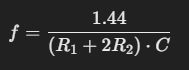
- Adjusting R2:
- By varying R2 (via a potentiometer or modulation circuit), you can vary the frequency fff continuously. For example, if R1=1kΩ, R2 varies from 1 kΩ to 10 kΩ, and C=10μF, the frequency will sweep over a range that you can calculate using the formula above.
6️⃣ Final Tips
- Experiment with Values:
- Start with typical values (e.g., R1=1kΩ, R2=5kΩ, C=10μF) and adjust as needed to get your desired siren effect.
- Sound Amplification:
- If the output sound is too weak, consider using a simple transistor amplifier circuit between the NE555 output and the speaker.
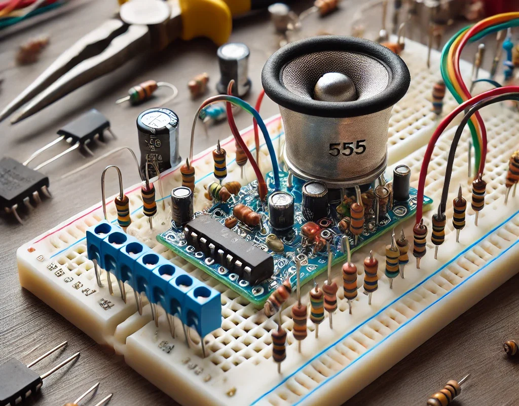
- Breadboard Testing:
- Use a breadboard for prototyping so you can easily tweak resistor and capacitor values for the best sound.
🎯 Conclusion
By configuring the NE555 in astable mode and adding a variable resistor or modulation circuit, you can create a dynamic siren sound. This project is a great example of how versatile the NE555 timer is and is perfect for learning about timing circuits and sound generation.