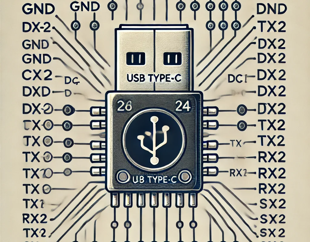
USB Type-C is a 24-pin reversible connector that supports power delivery, data transfer, and video output. Below is a pinout diagram and explanation of key pins.
1. USB Type-C Pinout Diagram
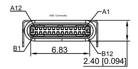
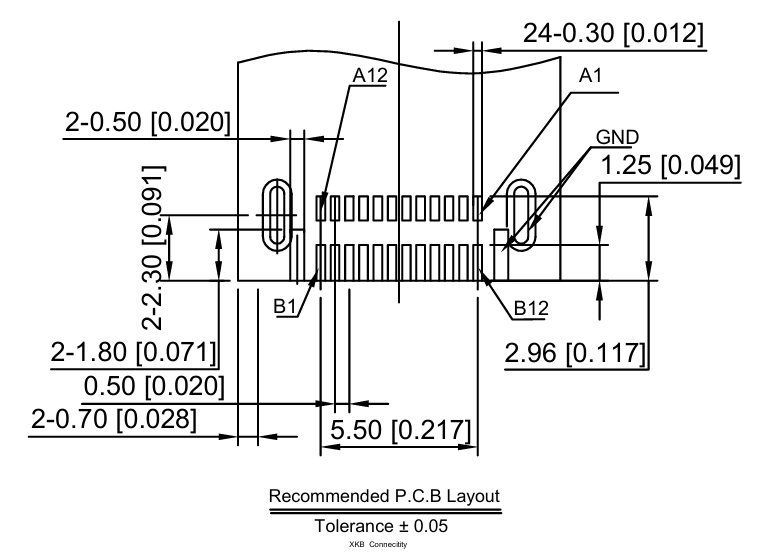
USB Type-C has two identical rows of 12 pins, making it reversible. The key functional groups are:
┌──────────────┬──────────────┐
│ A1  GND      │ B12  GND     │
│ A2  TX1+     │ B11  TX2+    │
│ A3  TX1-     │ B10  TX2-    │
│ A4  VBUS     │ B9   VBUS    │
│ A5  CC1      │ B8   SBU2    │
│ A6  D+       │ B7   D+      │
│ A7  D-       │ B6   D-      │
│ A8  SBU1     │ B5   CC2     │
│ A9  VBUS     │ B4   VBUS    │
│ A10 RX2-     │ B3   RX1-    │
│ A11 RX2+     │ B2   RX1+    │
│ A12 GND      │ B1   GND     │
└──────────────┴──────────────┘
2. Key Pins and Their Functions
| Pin | Function | Description |
|---|---|---|
| VBUS (A4, A9, B4, B9) | Power (5V to 20V) | Provides power to devices. |
| GND (A1, A12, B1, B12) | Ground | Common ground reference. |
| CC1 (A5), CC2 (B5) | Configuration Channel | Used for orientation detection and power negotiation. |
| D+ (A6, B7), D- (A7, B6) | USB 2.0 Data Lines | Standard USB 2.0 communication. |
| TX/RX (A2, A3, A10, A11, B2, B3, B10, B11) | High-Speed Data Transfer | Used for USB 3.0 and USB 3.1 communication. |
| SBU1 (A8), SBU2 (B8) | Sideband Use | Used for alternate modes (e.g., DisplayPort, Thunderbolt). |
3. USB Type-C Basic Wiring for Power
If you are using USB Type-C for power (5V output), connect:
- VBUS → 5V
- GND → GND
- CC1 or CC2 → 5.1kΩ resistor to GND (for device detection)
⚠️ Important:
- Without a 5.1kΩ pull-down resistor on CC1 or CC2, some devices may not power on.
- For USB Power Delivery (PD), you need an IC to negotiate higher voltages (e.g., 9V, 12V, 20V).
4. USB Type-C to USB 2.0 Wiring Example
To connect a USB Type-C plug to a USB 2.0 device:
USB Type-C   →   USB 2.0
--------------------------
VBUS (A4, B4) →  5V (Red)
GND (A1, B1)  →  GND (Black)
D+ (A6, B7)   →  D+ (Green)
D- (A7, B6)   →  D- (White)
CC1 (A5)      →  5.1kΩ to GND
CC2 (B5)      →  5.1kΩ to GND