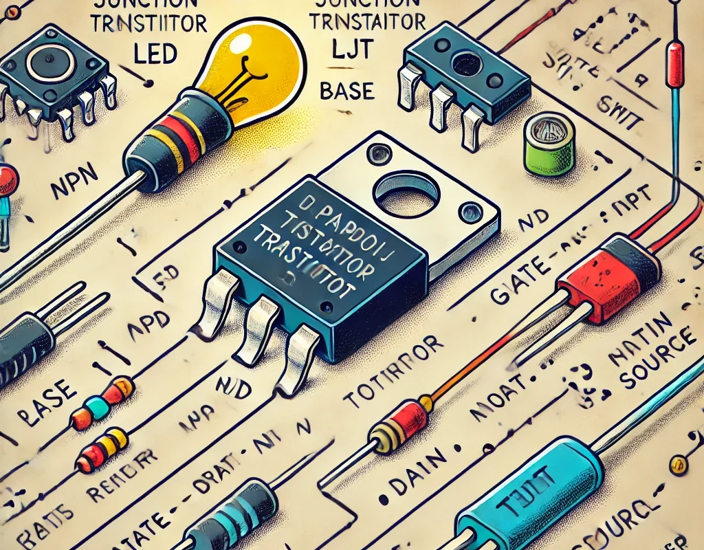
A switching transistor is a transistor used as an electronic switch to control high-power loads with low-power signals. It operates in two states:
- ON (Saturation Mode) – Acts as a closed switch (low resistance).
- OFF (Cutoff Mode) – Acts as an open switch (high resistance).
Switching transistors are widely used in digital circuits, motor drivers, power supplies, and microcontroller applications.
1. Types of Switching Transistors
🔹 Bipolar Junction Transistors (BJT)
- Common Types: NPN, PNP
- Best for: Low to medium power applications
- Example: 2N2222 (NPN), BC547 (NPN), BC557 (PNP)
- Operation:
- NPN: Turn ON when base receives current.
- PNP: Turn ON when base is pulled low.
🔹 Field Effect Transistors (FET)
- Common Types: MOSFET (N-channel, P-channel)
- Best for: High-speed and high-power applications
- Example: IRF540 (N-channel), IRF9540 (P-channel)
- Operation:
- N-Channel MOSFET: Turns ON when gate voltage > source voltage.
- P-Channel MOSFET: Turns ON when gate voltage < source voltage.
2. How a Transistor Works as a Switch
🔹 (A) Using a BJT as a Switch
Circuit Diagram (NPN Example)
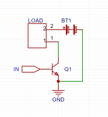
How It Works:
- LOW signal (0V) → Transistor OFF → No current flows → Load OFF.
- HIGH signal (e.g., 5V) → Transistor ON → Current flows → Load ON.
🔹 (B) Using a MOSFET as a Switch
Circuit Diagram (N-Channel MOSFET Example)
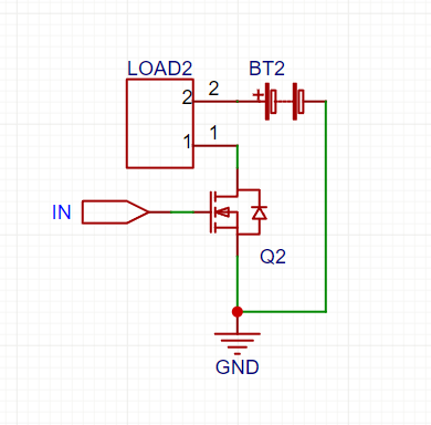
How It Works:
- LOW signal (0V) → MOSFET OFF → No current → Load OFF.
- HIGH signal (>5V or >10V for high-power MOSFETs) → MOSFET ON → Load ON.
3. Choosing the Right Switching Transistor
| Parameter | BJT (e.g., 2N2222) | MOSFET (e.g., IRF540) |
|---|---|---|
| Control Type | Current-based | Voltage-based |
| Switching Speed | Moderate | Very Fast |
| Power Handling | Moderate (Low-amp loads) | High (Heavy loads) |
| Efficiency | Lower (wastes power) | Higher (low resistance) |
| Gate/Base Drive | Needs base resistor | Needs voltage level shifting |
🔹 Use BJTs when switching small loads (LEDs, relays).
🔹 Use MOSFETs for high-power applications (motors, high-watt LEDs).
4. Applications of Switching Transistors
✅ Microcontroller Interfacing – Controlling LEDs, relays, and motors with Arduino/Raspberry Pi.
✅ Power Electronics – MOSFETs in SMPS (Switch Mode Power Supplies) and inverters.
✅ Motor Drivers – H-bridges use BJTs or MOSFETs to drive DC motors.
✅ Signal Amplification – Used in digital and analog signal processing.
5. Key Design Considerations
- For BJTs: Always use a base resistor (1kΩ to 10kΩ) to limit current.
- For MOSFETs: Choose logic-level MOSFETs if driving with 3.3V or 5V.
- For High-Power Loads: Use heat sinks to prevent overheating.
- For Fast Switching: Use pull-down resistors (10kΩ) on MOSFET gates.
🎯 Summary
- BJTs are good for small loads but need current control.
- MOSFETs are better for high power & efficiency and use voltage control.
- Used in relays, motors, microcontrollers, and power circuits.
- Always calculate resistor values and use heat sinks for high currents.