Three light-emitting diodes (LEDs) can display a number from one to six. The interesting experiment is deciding which number to display. A tiny program can give each face exactly the same count over a complete cycle while remaining completely predictable after reset. This project separates distribution, timing and unpredictability instead of calling every changing number random.
Exact parts and operating conditions
Use Microchip ATtiny85-20PU in an eight-pin plastic dual-inline package (PDIP), a regulated 3.3 V supply, three Kingbright WP7113ID red LEDs, three 1 kΩ resistors, two 10 kΩ resistors, a normally open pushbutton and 100 nF ceramic bypass capacitor. Resistors rated at least 0.125 W are ample. This is bare AVR C for an actual1 MHz processor clock, with avr-libc2.3.0 interfaces. The portable core is tested on a desktop; the AVR adapter has not been compiled or executed on the target.
The ordinary ATtiny85 grade supports2.7–5.5 V. At 3.3 V,1 MHz is within its operating region. Do not confuse the 20 MHz suffix with permission to use20 MHz at this supply. Use the internal8 MHz oscillator with divide-by-eight fuse enabled, reset enabled, debugWIRE disabled, clock output disabled and watchdog-always-on fuse unprogrammed. Confirm the actual fuse readback before programming; defining F_CPU does not set hardware fuses. Brown-out detection must permit the chosen supply.
Wire the binary display
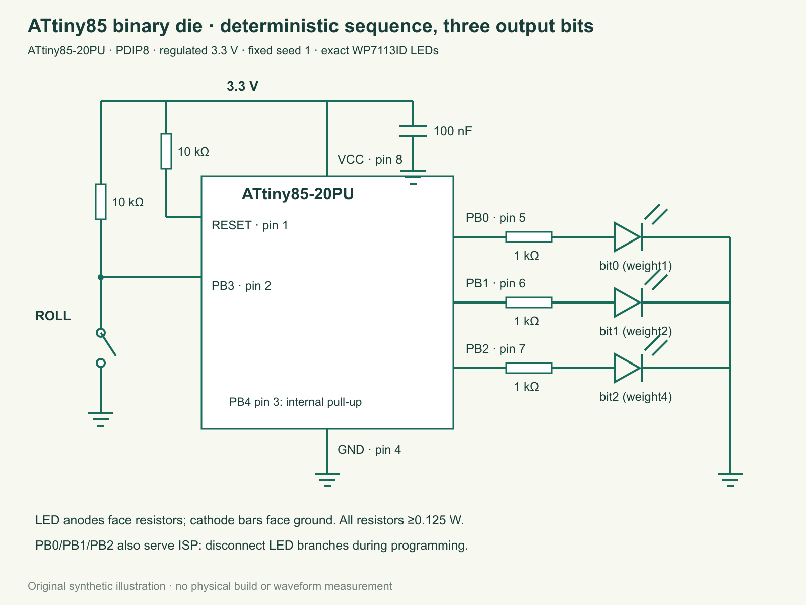
Supply pin 8 and ground pin 4 power the chip. Put100 nF directly across them. Reset pin 1 is held high through10 kΩ. PB3 at physical pin 2 reads the roll button: its10 kΩ pull-up defines released HIGH, and pressing connects it to ground. PB0/1/2 at pins 5/6/7 drive the separate LED resistor/anode branches. Cathodes return to ground. PB4 pin 3 remains unused with its internal pull-up enabled. The in-system programming (ISP) signals share the three display pins; disconnect the LED branches during programming and avoid powering the board from two sources.
Label the output weights1,2 and 4. A display of weights1 and 4 means five; it is a binary representation, not three ordinary die spots. Zero means no accepted roll yet. The program never displays seven. An illustrative2.0 V LED drop gives about(3.3−2.0)/1000=1.3 mA. That voltage is an assumption, not a guaranteed drop at this current. Even a zero-drop upper bound is3.3 mA per branch; at most two LEDs are on for faces1–6, so the conditional display bound is6.6 mA. Actual port voltage and brightness still need checking.
A repeatable sequence is useful evidence
A linear-feedback shift register (LFSR) updates a binary state using shifts and exclusive-OR operations. Exclusive OR is true when its two input bits differ. Here a 16-bit state shifts right; when the old low bit was one, the result is combined using exclusive OR with hexadecimalB400. Starting from seed one, the supplied host check visits every nonzero16-bit state once before repeating:65535 states. Zero is a trap and is rejected as an initial state.
A seed is the starting state. This program intentionally uses the same seed after every reset. It advances only when a settled button press requests a roll. Repeating the reset and press sequence therefore repeats the faces. Human timing is not sampled into the generator, and a noisy input is not asserted to be a source of entropy, the unpredictable information needed for an unpredictable result. This is a learning die, not a lottery, password or security generator.
Why direct modulo is slightly biased
Modulo means the remainder after integer division. Mapping all states 1–65535 with 1+(state−1)%6 assigns10923 states to faces1,2 and 3 but10922 to faces4,5 and 6. Three extra states cannot be shared evenly. Rejection sampling first refuses65533,65534 and 65535, leaving65532 states, exactly10922 per face. A rejected state advances again rather than becoming an extra roll.
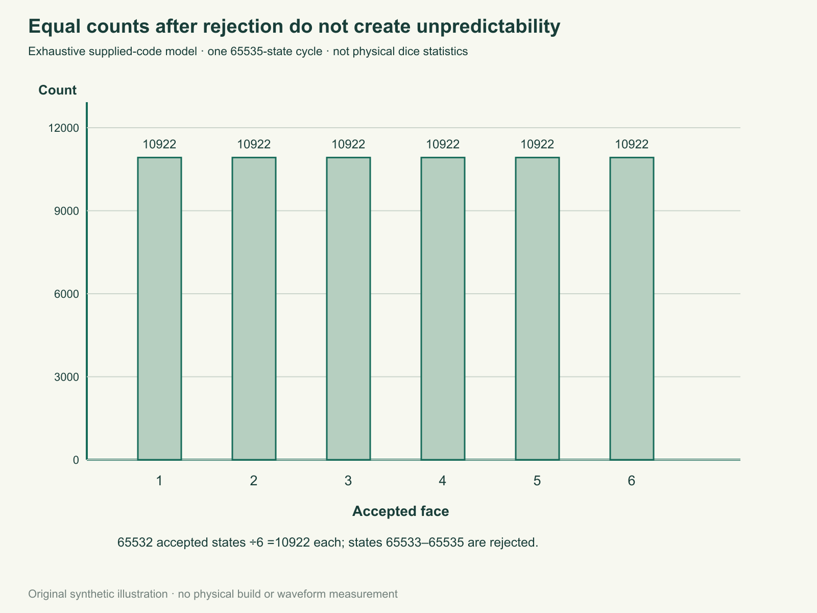
The bounded roll function allows at most16 state advances and faults if no accepted face appears or the sequence reaches zero. The supplied check also starts a roll from every nonzero seed. Those exhaustive deterministic checks establish the properties of this implementation. They do not mean a short physical run must contain equal counts, that successive faces are independent, or that a player cannot predict the next face.
Complete program and input behavior
The button must remain in one sampled level for 30 calls before that level is accepted. Startup is disarmed until a settled release, so holding the button while powering up does not roll. One settled press gives one face, a long hold gives no additional roll, and another settled release is required before the next. Each loop requests a one-millisecond delay, but software overhead and oscillator tolerance make this sample-count debounce rather than a calibrated30ms timer. A fault blanks the display and stops; it does not fabricate a face.
The early initialization fragment disables a leftover watchdog before normal startup, following avr-libc guidance; it does not change the watchdog fuse. The displayed face lives in volatile memory and is lost on power removal. No nonvolatile writes or hidden randomness library are used.
Download full source (ZIP; file: tricky-circuit-batch008-campaigns75-80/code/attiny-die-rejection.c) · Blank roll worksheet (ZIP; file: tricky-circuit-batch008-campaigns75-80/code/attiny-die-rejection-observations-blank.csv)
/* ATtiny85-20PU, 1 MHz CPU / avr-libc 2.3.0. No entropy claim. */
#include <stdint.h>
typedef struct { uint16_t state; uint8_t face, raw, stable, run, armed; } Die;
uint16_t lfsr_next(uint16_t x) {
    return (uint16_t)((x >> 1) ^ ((x & 1u) ? 0xb400u : 0u));
}
int face_from_state(uint16_t x) {
    return (x == 0 || x > 65532u) ? 0 : (int)((x-1u)%6u)+1;
}
int die_init(Die *d, uint16_t seed) {
    *d=(Die){seed,0,1,1,0,0};
    return seed != 0;
}
int roll(Die *d) {
    for (uint8_t i=0;i<16;i++) {
        d->state=lfsr_next(d->state);
        if (!d->state) return -1;
        int face=face_from_state(d->state);
        if (face) { d->face=(uint8_t)face; return face; }
    }
    return -1;
}
/* Call once per observed button sample; raw must be integer0/1. */
int sample(Die *d, uint8_t raw) {
    if (raw>1) return -1;
    if (raw != d->raw) { d->raw=raw;d->run=1; }
    else if (d->run<30) d->run++;
    if (d->run<30) return 0;
    if (raw) { d->stable=1;d->armed=1;return 0; }
    if (d->stable && d->armed) {
        d->stable=0;d->armed=0;
        return roll(d);
    }
    return 0;
}
#ifndef HOST_TEST
#define F_CPU 1000000UL
#include <avr/io.h>
#include <avr/wdt.h>
#include <util/delay.h>
void early_watchdog_off(void) __attribute__((naked,section(".init3"),used));
void early_watchdog_off(void) { MCUSR=0;wdt_disable(); }
int main(void) {
    PORTB=_BV(PB4); /* unused PB4 internal pull-up; PB3 uses external10k */
    DDRB=_BV(PB0)|_BV(PB1)|_BV(PB2);
    Die d;die_init(&d,1); /* fixed seed makes reset replay deliberate */
    for (;;) {
        int result=sample(&d,(PINB&_BV(PB3)) ? 1 : 0);
        if (result<0) {PORTB=_BV(PB4);for(;;){} }
        PORTB=(uint8_t)(_BV(PB4)|(d.face&7u));
        _delay_ms(1); /* sample-count debounce, not a calibrated30ms timer */
    }
}
#endif
Run a repeatable comparison
- Inspect unpowered connections and LED polarity; verify supply and fuse configuration before loading a target build. Record chip marking, clock configuration and tool versions.
- Hold the roll button while starting. The display should remain blank until release and a later settled press. Try short contact flickers and long holds; record accepted rolls separately from raw contact changes.
- Record twenty faces, reset, then repeat the same number of settled presses. The fixed-seed sequence should repeat. A different sequence requires investigating reset, code or input handling, not declaring new entropy.
- Compare direct modulo counts with the rejection histogram using the supplied portable core. Keep calculated counts separate from actual observed rolls.
- Collect a longer physical run if desired, but do not use six nearly equal bars as proof of security or independence. Record omissions and duplicated presses as possible input errors.
Challenge: all six faces appear exactly100 times. Does that prove unpredictability? Answer: no. A printed list cycling1–6 also has that histogram. Sequence structure, seed disclosure and predictability are separate questions.
Seven actual portable-code groups check the full cycle and distribution, rolls from all nonzero seeds, the zero trap, fixed-seed replay, startup hold, settled press/hold and invalid/bouncing input. Those checks exclude the AVR branch and do not establish a firmware binary, physical clock, measured LED current or hardware behavior. The bench log is empty.
Primary sources and limits
- Microchip ATtiny85 product
- Complete ATtiny datasheet2586Q
- Kingbright exact LED Rev14A
- avr-libc2.3.0 delay
- avr-libc watchdog initialization
The current Microchip product page and manufacturer-hosted complete2586Q datasheet were checked. Its ATtiny85 errata distinguish silicon revisions; the listed early electrically erasable programmable read-only memory (EEPROM) read issue does not affect this program, which does not use that memory. The physical revision remains unverified. Kingbright’s current exact sheet is revision 14A. Before building, consult those sources again and use the electronics lessons for resistor, LED and supply fundamentals.
Download the reader files (ZIP): complete source code, the blank observation worksheet and original editable SVG/PNG diagrams for attiny-die-rejection are inside tricky-circuit-batch008-campaigns75-80/. The inline program is complete; the download is supplementary.