Build the same red and blue pair twice. First place one current-limiting resistor before the branches split. Then give each branch its own resistor. Read the voltage across a small resistor already in each branch to see how much current each light-emitting diode (LED) draws. This comparison reports electrical current, which is the rate of flow of electric charge.
Parts and exact polarity
- D1 is the Kingbright WP7113ID red 5 mm through-hole LED, and D2 is the Kingbright WP7113QBC/D blue 5 mm through-hole LED. The manufacturer drawings mark the shorter untrimmed lead as cathode, K. The longer lead is anode, A. The diode bar in each schematic is the cathode. If the leads were cut, identify the cathode from the actual package drawing and a low-current diode test that supports the LED’s forward voltage, or use a known untrimmed part.
- Use an isolated regulated direct-current (DC) bench supply with a 4.50 V setpoint and a 10 mA current limit. The negative terminal is the circuit’s reference ground, GND. A volt (V) is a unit of voltage and a milliampere (mA) is one thousandth of an ampere.
- R1 is 499 Ω, R2 and R3 are 1.00 kΩ each, and RS1 and RS2 are 10 Ω each. Use ±1%, at least 0.25 W resistors. An ohm (Ω) is a unit of resistance, a kiloohm (kΩ) is 1,000 ohms, and a watt (W) is a unit of power. A ballast resistor limits current by dropping more voltage as current rises. A sense resistor is a known resistance used to infer current from its voltage drop.
- Use a digital multimeter (DMM) with a high-impedance DC voltage input of at least 1 MΩ and a millivolt range suitable for the readings. A millivolt (mV) is one thousandth of a volt. Use a meter or resistance measurement method that resolves the two 10 Ω values with a documented error bound, accounting for the test leads.
At 25 °C the red datasheet specifies a typical forward voltage of 1.9 V and maximum of 2.3 V at 10 mA. The blue datasheet specifies 3.3 V typical and 4.0 V maximum at 20 mA. Forward voltage is the drop across the LED while it conducts. These test points are useful context for the different branches. Actual voltage depends on current, temperature and the part in your hand. Both parts list 30 mA continuous forward current and 5 V reverse voltage as absolute maxima at 25 °C. The lab operates well below the forward current rating. The blue part is sensitive to electrostatic discharge, a sudden transfer of static charge, so use normal grounded static-control handling before assembly.
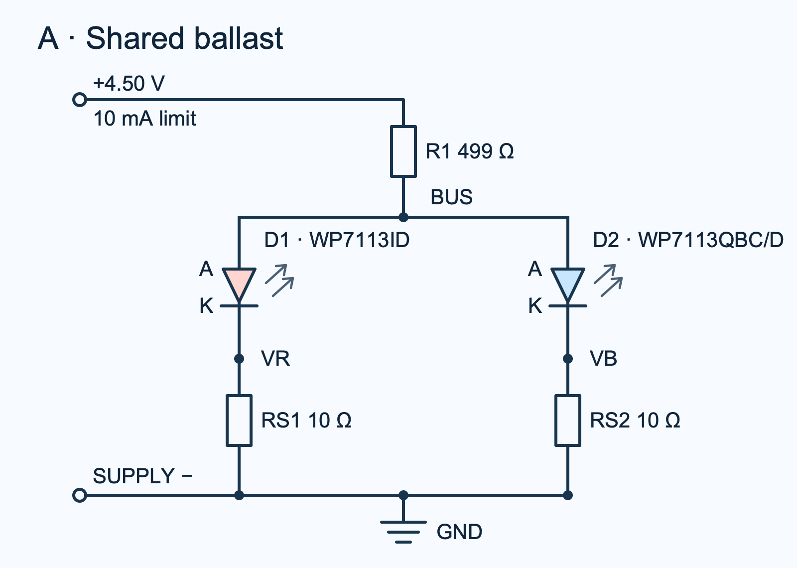
A. One resistor feeds both branches
With the output off, wire supply positive to R1. Connect the other end of R1 to both LED anodes at BUS. Connect the red cathode to the top of RS1 at VR, and the blue cathode to the top of RS2 at VB. Join the bottoms of both sense resistors to supply negative. RS1 and RS2 remain in these positions for the entire experiment.
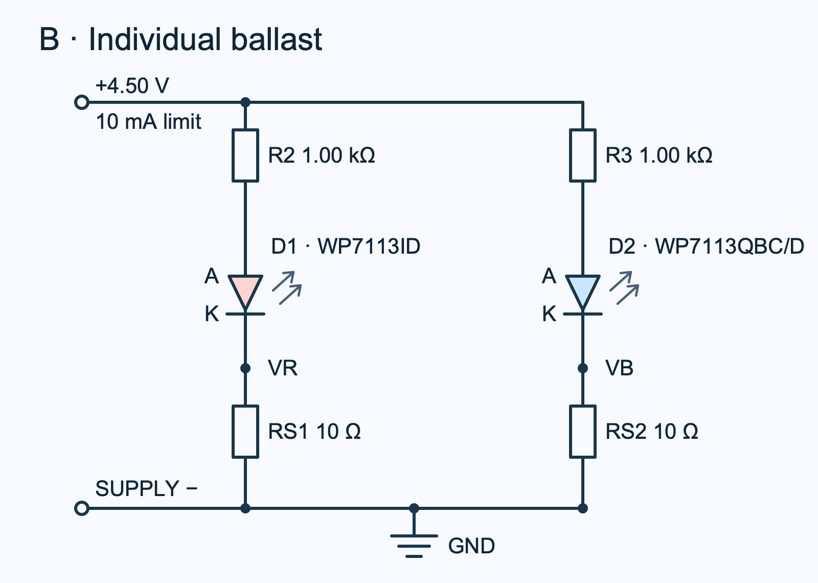
shared-ballast.svg)B. Each branch has its own resistor
Switch the supply output off before changing wires. Remove R1 and the link between the LED anodes. Feed the red anode from supply positive through R2 and feed the blue anode from supply positive through R3. Keep the cathodes, sense resistors and ground return exactly as before. The two anodes now have separate feed nodes.
individual-ballast.svg)Start and measure
- With the fixture disconnected and unpowered, measure the two sense resistors one at a time with no parallel path. Use the meter’s lead-zero function or account for the shorted-lead reading, and record the corrected values and an uncertainty bound in ohms. Reconnect the resistors. Set the supply voltage and current limit with the supply’s documented controls. With output disabled, trace both ground returns and both diode orientations, and check that neither diode bypasses its ballast or sense resistor.
- Connect supply negative to GND and positive to the marked supply input. Put the DMM black lead in the COM (common) jack and the red lead in the voltage jack. Set DC volts. Secure the black probe at GND. Turn on the supply and verify constant-voltage mode, CV, with 4.40–4.60 V at the fixture input. Switch off if the supply is in constant-current mode, CC, or if the voltage is outside that window. Inspect wiring before repeating.
- After the readings settle, keep the black probe at GND. Use the red probe to read VR and VB on the same millivolt range, one at a time. Record their signed readings. Read VR again and repeat the pair if it drifts appreciably during the interval. Record a conservative voltage error bound from the meter specification for the selected range, its digits and any observed zero offset or drift.
- Turn off before rewiring and repeat in configuration B at the same nominal supply setting. Aim for no more than 0.05 V difference between the two input readings. Run three paired trials if time allows. Keep the same two LEDs, sense resistors and meter setup and record the run order. Keep the probes away from adjacent powered terminals while moving them.
The meter stays in voltage mode across each installed resistor. An ammeter inserted in series would add a meter-dependent voltage drop, called burden voltage. Here the fixed resistor contributes its own small drop in both circuits. A 10 Ω resistor drops about 50 mV at 5 mA. A 1 MΩ voltmeter across 10 Ω adds at most about 0.001% of the sense-resistor current through its input. The calculated branch current neglects that small diversion. The installed sense resistors can still slightly alter how the LEDs share current, so keep them in place across both runs.
Convert the readings to current
Use Ohm’s law, I = V/R. A reading in millivolts divided by a measured resistance in ohms gives milliamperes. Divide the red branch current by the blue branch current to get the red-to-blue ratio. Add the branch currents to estimate the total. The ratio measures electrical sharing. The LEDs have different wavelengths and optics, so current and perceived brightness are separate observations.
Use the meter error bounds at both ends of the calculation. With voltage V, error eV, resistance R and error eR, the lower current bound is max(0, V − eV)/(R + eR), and the upper bound is max(0, V + eV)/(R − eR). These are conservative bounds under the stated meter assumptions. A small negative reading inside the error bound can include zero. A reading more negative than the error bound calls for checking probe polarity or offset. When the blue lower bound is zero, you can report a finite lower ratio bound if the blue upper bound is positive and red is resolved. The upper ratio is unresolved, and an exactly zero blue current leaves division undefined.
For the supplied synthetic input, shared reads 53.5 mV red and 0.10 mV blue, while individual reads 27.2 mV red and 17.8 mV blue. Both sense resistors are entered as 10.00 Ω with ±0.02 Ω and the voltage error is ±0.30 mV. The shared blue current is bounded above by about 0.040 mA, and the red-to-blue ratio is at least about 132 where the blue current is nonzero. The individual example yields 2.72 mA red and 1.78 mA blue, with a ratio of about 1.53. These example inputs are synthetic. Use your recorded voltages to decide what your pair actually does.
What moves when one branch draws more?
With shared ballast, the current through R1 is the sum of the branch currents. More current means more voltage drop across R1, which reduces BUS voltage for both branches. BUS also equals each LED’s own forward drop plus that branch’s sense drop. At room temperature the lower-forward-voltage red branch may therefore draw almost all the current and leave blue below the measurement resolution.
With individual ballast, each branch uses its own resistor drop. For example, the red loop obeys supply voltage = red LED drop + red current × (R2 + RS1). An increase in red current raises the drop in the red ballast without taking the same voltage from the blue branch’s ballast. Different forward voltages still mean different currents. For equal hypothetical LED drops, the two circuits have nearly the same nominal equivalent series resistance, 499 Ω + (10 Ω ∥ 10 Ω) = 504 Ω versus (1,000 Ω + 10 Ω) ∥ (1,000 Ω + 10 Ω) = 505 Ω. The ∥ sign means two paths in parallel. That comparison helps separate the effect of where ballast sits from a large change in equivalent resistance.
Read a fault before drawing a conclusion
- Blue is near zero in both configurations
- Switch off and trace its anode feed, cathode orientation, sense resistor and return. Check for open or reversed wiring. A near-zero reading alone cannot distinguish these faults from insufficient forward voltage. Restore the exact circuit before retesting.
- Both readings are near zero
- Check that the supply is enabled, that its voltage reaches the positive fixture terminal and that the negative return is connected. Confirm the meter reference and the actual sense locations.
- A high sense reading accompanies a dark LED
- Power off and look for an LED bridged by a wire or damaged short. A short can increase branch current while the LED emits no light. Use a powered-off continuity check only after disconnecting the supply and isolating the path.
- The supply enters current limit or a sense resistor is bypassed
- Power off and check for a rail short, wrong ballast value or bypass. A bypassed sense resistor can show zero while its LED still draws current. Keep every resistor in place. With correctly installed ±1% ballast and sense resistors, even the arithmetic worst case with both LEDs replaced by shorts is about 9.22 mA for A and 9.20 mA for B at 4.60 V. The common ballast would dissipate under 43 mW by the conservative bound V²/R. These are calculated limits for those paths. A wiring short ahead of the ballast relies on the supply limit.
Run the complete analyzer
Use host Python 3.9 or later. The comma-separated values (CSV) worksheet records each pair as shared and individual under the same trial number. Enter CV, volts for supply, millivolts for sense drops, and ohms for measured sense resistances. Use the same resistance calibration for both rows. Remove unused trial pairs from your working copy. The program requires a voltage error bound up to 1.0 mV and a resistance error bound up to 0.10 Ω for this worksheet. If your meter cannot support those bounds, retain your raw readings and report the limit before comparing ratios.
Download the experiment ZIP (ZIP: led-sharing-lab.zip) or open the blank worksheet (ZIP: observations-blank.csv) and synthetic example (ZIP: synthetic-example.csv). Save the program as led_sharing.py (ZIP: led_sharing.py). Run python3 led_sharing.py synthetic-example.csv to verify the worked example, then substitute your completed worksheet. The program prints structured JavaScript Object Notation (JSON) with each current and ratio bound. A null bound means it could not resolve that endpoint from the readings.
"""Infer LED branch currents from recorded voltage-mode measurements."""
import argparse
import csv
import json
import math


FIELDS = (
    "trial", "topology", "supply_v", "mode", "red_mv", "blue_mv",
    "voltage_error_mv", "red_ohm", "blue_ohm", "resistance_error_ohm",
)
TOPOLOGIES = ("shared", "individual")


def number(row, field):
    try:
        value = float(row[field])
    except (ValueError, TypeError):
        raise ValueError(f"{field} requires a finite number") from None
    if not math.isfinite(value):
        raise ValueError(f"{field} requires a finite number")
    return value


def bounds(estimate, low, high):
    return {"estimate": estimate, "low": low, "high": high}


def current(voltage_mv, voltage_error, resistance, resistance_error):
    if voltage_mv < -voltage_error:
        raise ValueError("check polarity and the zero reading at the sense resistor")
    if voltage_mv > 110:
        raise ValueError("sense drop exceeds the 10 mA fixture range")
    return bounds(
        max(0.0, voltage_mv) / resistance,
        max(0.0, voltage_mv - voltage_error) / (resistance + resistance_error),
        max(0.0, voltage_mv + voltage_error) / (resistance - resistance_error),
    )


def analyze_row(row):
    try:
        trial = int(row["trial"])
    except (ValueError, TypeError):
        raise ValueError("trial must be a positive integer") from None
    if trial < 1 or row["topology"] not in TOPOLOGIES:
        raise ValueError("use a positive trial and shared or individual topology")
    supply = number(row, "supply_v")
    if row["mode"] != "CV":
        raise ValueError("use a constant-voltage (CV) run, not current-limit mode")
    if not 4.40 <= supply <= 4.60:
        raise ValueError("measured supply must be in 4.40–4.60 V")
    voltage_error = number(row, "voltage_error_mv")
    resistance_error = number(row, "resistance_error_ohm")
    if not 0 < voltage_error <= 1.0 or not 0 < resistance_error <= 0.10:
        raise ValueError("use positive uncertainty up to 1.0 mV and 0.10 ohm")

    red_r = number(row, "red_ohm")
    blue_r = number(row, "blue_ohm")
    if not all(9.80 <= resistance <= 10.20 for resistance in (red_r, blue_r)):
        raise ValueError("use measured sense resistance in 9.80–10.20 ohm")
    red = current(number(row, "red_mv"), voltage_error, red_r, resistance_error)
    blue = current(number(row, "blue_mv"), voltage_error, blue_r, resistance_error)
    total = {key: red[key] + blue[key] for key in red}
    if total["low"] > 10:
        raise ValueError("the lower total-current bound exceeds the 10 mA setting")

    ratio = bounds(
        red["estimate"] / blue["estimate"] if red["low"] > 0 and blue["low"] > 0 else None,
        red["low"] / blue["high"] if blue["high"] > 0 else None,
        red["high"] / blue["low"] if blue["low"] > 0 else None,
    )
    if any(value is not None and not math.isfinite(value) for value in ratio.values()):
        raise ValueError("ratio exceeds the supported numeric range")
    return trial, (red_r, blue_r, resistance_error), {
        "supply_v": supply, "red_ma": red, "blue_ma": blue,
        "total_ma": total, "red_over_blue": ratio,
    }


def analyze(stream):
    reader = csv.DictReader(stream)
    if tuple(reader.fieldnames or ()) != FIELDS:
        raise ValueError("CSV columns must match the supplied worksheet")
    pairs = {}
    for row in reader:
        if None in row or None in row.values():
            raise ValueError(f"line {reader.line_num}: use every worksheet column exactly once")
        try:
            trial, calibration, result = analyze_row(row)
        except ValueError as error:
            raise ValueError(f"line {reader.line_num}: {error}") from error
        pair = pairs.setdefault(trial, {})
        topology = row["topology"]
        if topology in pair:
            raise ValueError(f"trial {trial}: duplicate {topology} row")
        pair[topology] = (calibration, result)
    if not pairs:
        raise ValueError("enter a measured or example pair before running the analyzer")

    results = []
    for trial, pair in sorted(pairs.items()):
        if set(pair) != set(TOPOLOGIES):
            raise ValueError(f"trial {trial}: enter both topologies")
        shared_calibration, shared = pair["shared"]
        individual_calibration, individual = pair["individual"]
        if shared_calibration != individual_calibration:
            raise ValueError(f"trial {trial}: use the same sense calibration in both rows")
        if abs(shared["supply_v"] - individual["supply_v"]) > 0.05 + 1e-12:
            raise ValueError(f"trial {trial}: supply readings differ by more than 0.05 V")
        results.append({"trial": trial, "shared": shared, "individual": individual})
    return {"trials": results}


def main():
    parser = argparse.ArgumentParser(description=__doc__)
    parser.add_argument("csv_file", help="completed worksheet or the labeled synthetic example")
    options = parser.parse_args()
    try:
        with open(options.csv_file, newline="", encoding="utf-8-sig") as stream:
            results = analyze(stream)
    except (OSError, UnicodeError, csv.Error, ValueError) as error:
        parser.error(str(error))
    print(json.dumps(results, indent=2, allow_nan=False))


if __name__ == "__main__":
    main()
Try one change on paper
Predict what happens if the red branch opens
If D1 opens, its current falls to zero. In configuration A, R1 no longer drops voltage for red current, so BUS can rise and the intact blue branch may start conducting more. In configuration B, the blue loop keeps its own R3 and RS2, so its current should change little if the supply stays regulated. If the supply was in current limit before the change, the two conditions are not a clean comparison.
Sources and verification
- Kingbright WP7113ID, V.14A and WP7113QBC/D, V.18B. The package drawings, ratings and typical curves are on pages 1–3.
- See also how the TLC5916 constant-current driver needs voltage headroom.
The analyzer was exercised on a host computer with synthetic readings. This article provides an unmeasured bench procedure and a blank worksheet.
Download the complete reader files (ZIP): the original editable drawing, PNG, worksheet and code in led-shared-ballast-current. The full main program is also included above.