
Put the drain of a P-channel AO3401A at the raw input and its source at a one-kilohm load. With positive input, measure the voltage drop first with the gate tied to the source, then with the gate tied to the circuit return. Finally, reverse only the floating supply leads and measure the output again. The three readings let you trace where current can flow and see how the gate changes the positive-input path.
A metal–oxide–semiconductor field-effect transistor (MOSFET) controls conduction between its drain and source through the voltage at its gate. On this P-channel device, a gate sufficiently below the source allows the channel to conduct. The body diode is an inherent junction inside the device. Its anode is at the drain and its cathode is at the source, so it can pass conventional current from drain to source even when the gate and source are tied together.
This lab uses steady direct-current (DC) measurements on a passive load. Use the blank worksheet for your own readings. The example readings below are constructed to demonstrate the calculations.
Identify the AO3401A before wiring
Use the Alpha and Omega Semiconductor (AOS) AO3401A in its three-lead small-outline transistor package, SOT23. In the manufacturer’s top view, rotate the drawing so the single lead points up. That lead is drain pin 3. The two lower leads are gate pin 1 on the left and source pin 2 on the right. AOS’s marking document PD-00660 version C assigns the part-number code X1 to both AO3401A and AO3401AL. Keep the package or reel label that identifies the exact AO3401A, then trace the bare adapter’s numbered pads to its pins with power disconnected.
Build a resistor-only fixture
- One AO3401A and a plain SOT23 adapter that exposes all three leads.
- One 1.00 kΩ, 1%, ¼ W resistor. Measure its resistance before connection.
- One floating bench supply output set to 3.30 V with a 10 mA limit, verified per the supply manual. Floating means neither output terminal is bonded to earth. Use a single output and keep any earth link disconnected.
- One battery-powered digital multimeter, in its direct-voltage mode with the black lead in common (COM) and red lead in the voltage jack. Use insulated clips and one removable insulated gate jumper. Keep external power, Universal Serial Bus (USB) cables, oscilloscopes, output capacitors and powered loads off this fixture.
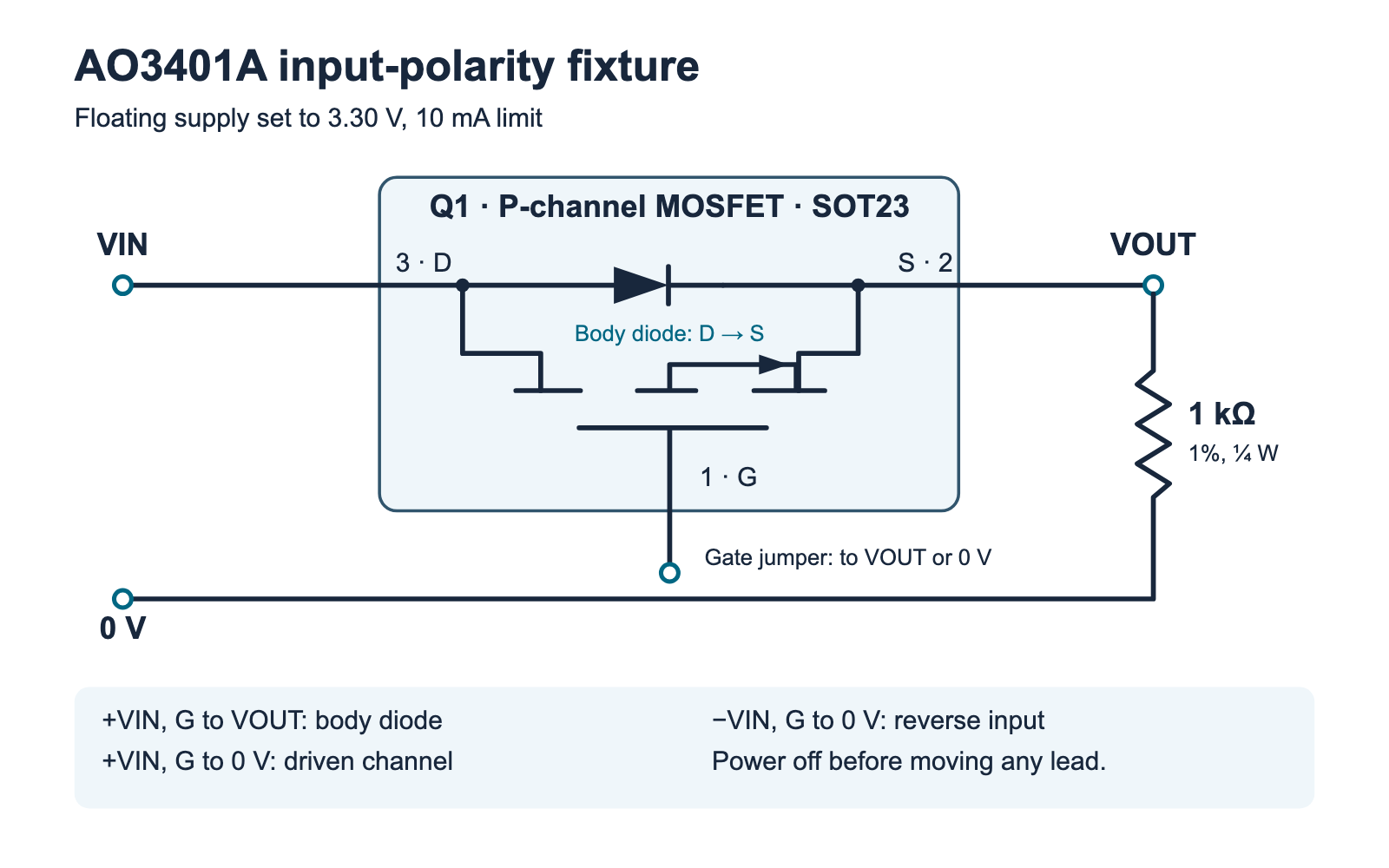
fixture.svg)| Terminal | Connection |
|---|---|
| Drain, pin 3 | Raw input, VIN. The supply lead at this point determines the test polarity. |
| Source, pin 2 | Output, VOUT. The 1 kΩ load connects from here to the fixed 0 V circuit return. |
| Gate, pin 1 | One jumper to VOUT or to the circuit return, as specified in the case table. Never enable power with the gate jumper removed or with both ties fitted. |
| Circuit return | The other supply lead, the low end of the load resistor and the black meter lead. This circuit node stays the reference when the supply leads swap. |
At the top of the worksheet’s allowed input range, 3.35 V across 985 Ω would draw 3.40 mA and dissipate about 11.4 mW in the load. These arithmetic bounds describe the resistor branch. Keep the supply’s 10 mA limit active and switch off immediately if it enters current limit, the voltage changes unexpectedly, or anything warms.
Measure the three cases
Disable and physically disconnect the floating supply from the fixture before moving either supply lead or the gate jumper. Check for zero residual voltage from VIN and VOUT to return. Complete the new wiring before reconnecting the disabled supply and enabling it. Never reverse an energized input. Before each connection, identify the supply leads. If you verify their polarity with the meter, enable the output only while it is disconnected from the fixture, then disable it and confirm the lead voltage has returned to zero.
| Worksheet case | Supply leads | Gate tie |
|---|---|---|
positive_diode |
Positive to VIN, negative to return | VOUT (source) |
positive_channel |
Positive to VIN, negative to return | Return (0 V) |
negative_input |
Negative to VIN, positive to return | Return (0 V) |
- Start with
positive_diode. With the black meter lead at return, measure VIN, the gate and VOUT in turn. Confirm the gate and source agree. Their difference, VGS, is approximately zero because of the jumper. The body diode can conduct and VOUT should sit below VIN under load. - Power down and move the gate tie to return. Repeat the three readings for
positive_channel. The diode initially raises the source. The grounded gate is then negative relative to the source, allowing the channel to carry current in parallel with the diode. Look for a smaller VIN minus VOUT drop under a similar input voltage. - Power down and reverse only the floating supply leads. Keep the gate tied to return. In
negative_input, expect a negative VIN while the resistor holds VOUT close to return. With the diode’s anode below its cathode and little gate-to-source voltage, the main conduction paths are off. If the output is materially displaced from 0 V, switch off and verify lead and pin orientation before proceeding. Record the signed reading. Return the bench setup to an unpowered state afterward.
Use the same meter range and wait for stable values. You can also measure the small drop directly with red on drain and black on source, using a suitable DC range on the floating meter. Compare that reading with the difference of the two larger voltages. Near zero, resolution, accuracy and probe contact can dominate that difference. In the reverse case, a displayed 0 V is only a reading within the meter’s capability.
Calculate the voltage and current differences
Compute gate-to-source voltage as VGS = VG − VOUT. The signed voltage between drain and source in this fixture is VIN − VOUT. Resistor current is VOUT divided by the measured load resistance. A negative value indicates current through that resistor toward the output node. Load power is VOUT squared divided by resistance. The meter introduces a small parallel path during its output reading.
| Case | VIN | VOUT | VGS | VIN − VOUT | Load current |
|---|---|---|---|---|---|
| Diode | 3.300 V | 2.850 V | 0.000 V | 0.450 V | 2.850 mA |
| Channel driven | 3.300 V | 3.299 V | −3.299 V | 0.001 V | 3.299 mA |
| Input reversed | −3.300 V | −0.002 V | 0.002 V | −3.298 V | −0.002 mA |
The AOS data sheet specifies body-diode forward voltage at a one-ampere current magnitude with VGS = 0 V. Its on-resistance row at VGS = −2.5 V uses a drain current of −2.5 A. Keep both conditions attached to their numbers. The data sheet’s ±12 V gate-to-source absolute maximum is a device stress limit. This fixture only uses a ±3.30 V input. The table above demonstrates calculation, and the lab calls for measuring the actual drops at a few milliamperes.
The scope is a resistive, unpowered output and a steady reversal performed with power off. Once a single MOSFET channel is on, it can carry current in either direction. An externally powered output can change the gate-to-source voltage and the current paths. The TPS22919 power-path lab demonstrates an alternate source and discharge path, while the AO3400A low-side lab examines a switch in the load return.
Run the worksheet program
Copy the blank comma-separated values worksheet (ZIP: observations-blank.csv) and enter VIN, gate voltage, VOUT and the same measured resistance in all three rows. Save the program as ao3401a_polarity.py and run python3 ao3401a_polarity.py observations.csv using Python 3.9 or later. The ZIP includes a constructed example and the host tests.
The program checks supply sign and magnitude, gate ties, resistance and plausible rail readings. It labels a reverse output within 50 mV of return as near the reference, a worksheet label chosen for this lab. Larger displacements within the fixture rails are preserved and flagged for a wiring check. Its decimal formatting does not add meter precision. Use the raw readings for diagnosis.
"""Compare three AO3401A polarity-fixture observations from a CSV sheet."""

import argparse
import csv
import math
from pathlib import Path
import sys

CASES = ("positive_diode", "positive_channel", "negative_input")
FIELDS = ("case", "vin_v", "gate_v", "vout_v", "load_ohm")
RESULT_FIELDS = (
    "case", "vgs_v", "vin_minus_vout_v", "load_ma", "load_mw", "output_observation",
)


def number(row, field):
    try:
        value = float(row[field])
    except (TypeError, ValueError):
        raise ValueError(f"{field} requires a number") from None
    if not math.isfinite(value):
        raise ValueError(f"{field} must be finite")
    return value


def read_case(row):
    case = row["case"]
    if case not in CASES:
        raise ValueError(f"unknown case: {case}")
    vin, gate, vout, load = (number(row, field) for field in FIELDS[1:])
    reversed_input = case == "negative_input"

    if not 985 <= load <= 1015:
        raise ValueError("load_ohm must be within the 1 kΩ fixture band")
    if reversed_input:
        if not -3.35 <= vin <= -3.25:
            raise ValueError("negative supply must be within −3.35 to −3.25 V")
    elif not 3.25 <= vin <= 3.35:
        raise ValueError("positive supply must be within +3.25 to +3.35 V")

    if not min(0, vin) - 0.020 <= vout <= max(0, vin) + 0.020:
        raise ValueError("vout_v lies outside the fixture rails and 20 mV allowance")
    if case == "positive_diode":
        if not vout - 0.020 <= gate <= vout + 0.020:
            raise ValueError("diode-mode gate must match source within 20 mV")
    elif abs(gate) > 0.020:
        raise ValueError("grounded gate must be near reference within 20 mV")
    return vin, gate, vout, load


def report(case, voltages):
    vin, gate, vout, load = voltages
    observation = "positive_reading"
    if case == "negative_input":
        if abs(vout) <= 0.050:
            observation = "reverse_output_near_reference"
        else:
            observation = "reverse_output_check_wiring"
    return (
        case, f"{gate - vout:.6f}", f"{vin - vout:.6f}",
        f"{1000 * vout / load:.6f}", f"{1000 * vout ** 2 / load:.6f}",
        observation,
    )


def read_sheet(stream):
    reader = csv.DictReader(stream, strict=True)
    if reader.fieldnames != list(FIELDS):
        raise ValueError("CSV header must be " + ",".join(FIELDS))
    cases = {}
    for row in reader:
        try:
            if None in row:
                raise ValueError("too many columns")
            case = row["case"]
            if case in cases:
                raise ValueError(f"duplicate case: {case}")
            cases[case] = read_case(row)
        except ValueError as exc:
            raise ValueError(f"row {reader.line_num}: {exc}") from exc

    missing = [case for case in CASES if case not in cases]
    if missing:
        raise ValueError("missing case: " + ", ".join(missing))
    load = cases[CASES[0]][3]
    if any(case[3] != load for case in cases.values()):
        raise ValueError("use the same measured load resistance in all cases")
    return [report(case, cases[case]) for case in CASES]


def main():
    parser = argparse.ArgumentParser(description=__doc__)
    parser.add_argument("sheet", help="measurement CSV path or - for standard input")
    args = parser.parse_args()
    try:
        if args.sheet == "-":
            results = read_sheet(sys.stdin)
        else:
            with Path(args.sheet).open(encoding="utf-8-sig", newline="") as stream:
                results = read_sheet(stream)
    except (OSError, UnicodeError, csv.Error, ValueError) as exc:
        parser.exit(2, f"{exc}\n")

    writer = csv.writer(sys.stdout, lineterminator="\n")
    writer.writerow(RESULT_FIELDS)
    writer.writerows(results)


if __name__ == "__main__":
    main()
Trace an unexpected reading
- Diode-case output stays at 0 V. With the supply disconnected, trace pin 3 to VIN and pin 2 to the load. Check whether the positive voltage really reached VIN.
- Grounding the gate produces little change. Check the recorded VGS and confirm that the jumper moved from source to return. Check the drop directly and compare readings at the same input setting.
- VOUT follows a reversed VIN. Disable the supply. A swapped drain and source can put the body diode in the opposite direction. Check the top-view package and every jumper before trying again.
Challenge
In the constructed diode case, how much of the input voltage reaches the load, and how much extra load current flows in the constructed driven-channel case?
Check your reasoning
2.850 V divided by 3.300 V is about 86.4%. The current changes from 2.850 to 3.299 mA, an increase of 0.449 mA with the same 1,000 Ω resistor. You can calculate both quantities from a completed worksheet using the two actual forward readings.
Primary references and files
- AOS AO3401A product page. Lists the manufacturer-linked data sheet and marking document.
- AOS AO3401A data sheet, Rev. 3.1, December 2023. Page 1 shows the terminals and internal diode. Page 2 gives the electrical test conditions.
- AOS AO3401A marking, PD-00660 version C and SOT23 package drawing, PO-00001 version N.
Download the experiment files (ZIP) (ZIP: experiment-tests-v1.zip). It includes the original schematic, full-size image, blank and constructed worksheets, complete program and host tests.
Download the complete reader files (ZIP): the original editable drawing, PNG, worksheet and code in ao3401a-input-polarity. The full main program is also included above.