A relay coil can be easy to turn on and surprisingly demanding to turn off. Current stores energy in the coil’s magnetic field. Interrupting the supply path does not make that energy vanish. A correctly connected diode gives the coil current a controlled route while it falls.
Your goal: understand the diode’s direction, build a protected low-voltage relay driver and distinguish a working relay from a verified transient waveform.
The coil and its current path
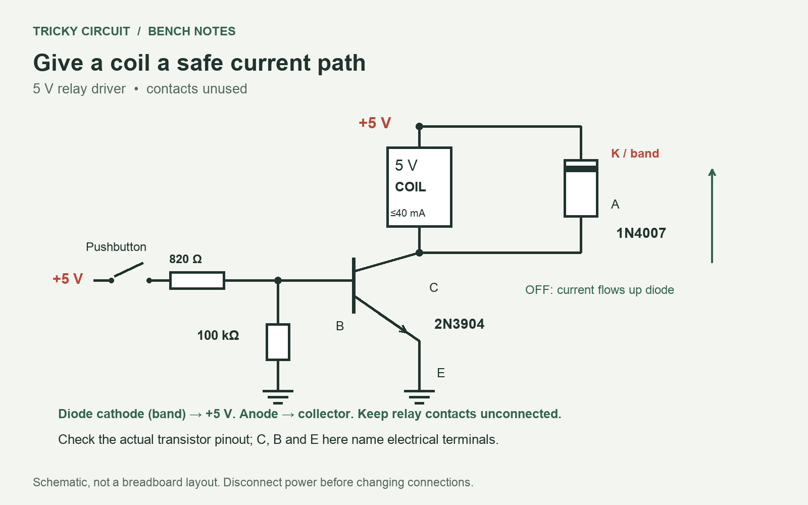
A relay uses an electromagnet to move electrical contacts. Its coil is an inductive load: it opposes a rapid change in current. When a low-side transistor opens the coil’s connection to ground, the coil drives its lower terminal upward in voltage to keep current flowing in the same direction through the winding.
A flyback diode, also called a freewheeling diode, connects across the coil. Put its cathode at the +5 V end and its anode at the transistor end. The cathode is marked by the bar in the symbol and usually a band on an axial diode. Verify the marking on the actual part.
While the transistor is on, the diode is reverse-biased and normally carries little current. After switch-off, the lower coil terminal rises above +5 V enough to make the diode conduct. Current goes up through the diode and down through the coil, circulating in a loop until the stored energy is dissipated.
Use a small bare coil for this demonstration
- A regulated 5 V direct-current (DC) supply.
- A bare 5 V relay with coil current no greater than 40 mA and specified pickup voltage no greater than 4.5 V. Check its actual coil pins and resistance in its datasheet.
- A 2N3904 NPN transistor. NPN identifies its n-type/p-type/n-type semiconductor regions. Check the emitter, base and collector pinout.
- A 1N4007 rectifier diode, an 820 Ω base resistor and a 100 kΩ base-to-emitter resistor; use 0.25 W resistors.
- A normally open pushbutton, breadboard, wires and multimeter.
This is an occasional on/off experiment, not a high-frequency motor controller. Use a bare relay without an internal diode, or follow the polarity requirements of its built-in suppression if it has one. Leave the relay’s contact terminals unconnected throughout the lesson.
Connect and check
- Disconnect power. Wire +5 V → relay coil → transistor collector, then emitter → supply negative, the common ground (GND).
- Add the diode directly across the coil: cathode to +5 V, anode to collector. Reversing it can short the supply through the transistor when the button is pressed.
- Wire +5 V → button → 820 Ω → base. Add 100 kΩ from base to emitter.
- Check the diode orientation and all transistor pins, then apply 5 V. Press the button briefly; the relay should operate. Release it; it should release.
- With the meter in voltage mode and leads in V and COM (common), check the coil voltage while on. If the relay does not operate, verify supply voltage, coil resistance and transistor collector voltage before changing parts.
A numerical example
Suppose a coil has 200 Ω resistance. At 5 V its nominal current is 5 / 200 = 0.025 A = 25 mA. If the transistor drops 0.2 V, the coil gets 4.8 V and the predicted current is 24 mA. Here A means ampere and mA means one thousandth of an ampere. Your relay may have a different resistance, so use its measured or specified value.
For an illustrative inductance of 100 millihenries, written 100 mH or 0.1 H, the energy at 25 mA is E = ½ × L × I² = 0.00003125 joules = 31.25 microjoules. L is inductance and I is current. Inductance can vary with the relay’s magnetic state; this is a calculation example, not a claim about your relay.
Using a 0.85 V base-to-emitter assumption, the base current is approximately (5 − 0.85) / 820 − 0.85 / 100,000 = 5.05 mA. Check transistor saturation and dissipation against the actual load. This manual button circuit avoids assuming a particular microcontroller pin can supply that current.
What the meter cannot prove
A normal multimeter may miss the short switch-off transient. A relay clicking does not prove that a voltage spike is within the transistor’s limits. Examining that waveform needs an appropriately connected oscilloscope and suitable measurement technique. Do not remove the diode to “see whether it still works.”
A plain diode also makes coil current decay more slowly than a higher-voltage clamp. That can delay relay release. Texas Instruments’ inductive-load explanation discusses freewheeling paths and energy dissipation. Faster release needs a properly designed clamp matched to the switch and relay, not simply a missing diode.
Check your understanding
Immediately after the transistor opens, does the current reverse in the coil? Which diode terminal belongs at +5 V?
Show the answer
The coil current initially continues in the same direction. Its voltage polarity changes to sustain that current through the new diode loop. The cathode belongs at +5 V; the anode belongs at the collector side.
Review the driver limits in the 2N3904 datasheet. For earlier switching concepts, start with Switching Transistors and the interactive laboratory.