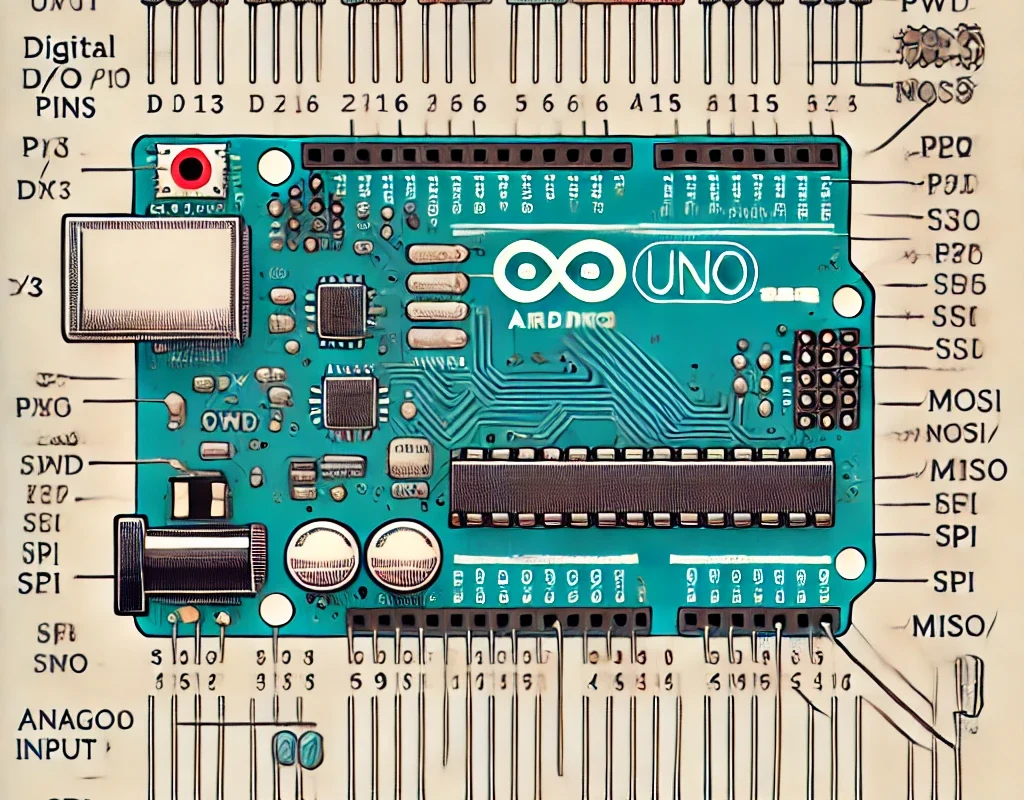
Arduino boards come with various types of pins, each serving a different function. Understanding these pins is essential for working with sensors, motors, displays, and communication modules.
🔹 1. Types of Arduino Pins
| Pin Type | Description |
|---|---|
| Power Pins | Provide voltage (5V, 3.3V) and ground (GND). |
| Digital Pins | Used for input/output (HIGH/LOW signals). |
| PWM Pins | Provide simulated analog output via pulse-width modulation. |
| Analog Pins | Read varying voltage values (0-1023 range). |
| Communication Pins | Used for UART (Serial), I2C, SPI communication. |
| Special Function Pins | Some pins have multiple functions (e.g., external interrupts, timers). |
🔹 2. Power Pins
| Pin | Function |
|---|---|
| 5V | Provides 5V output (for sensors, modules). |
| 3.3V | Provides 3.3V output (for low-voltage components like ESP8266). |
| GND | Ground (common reference for all components). |
| VIN | Voltage input (for external power supply, e.g., 7-12V). |
📌 Note: Some boards (like Arduino R4 WiFi) support USB-C power delivery with dynamic voltage regulation.
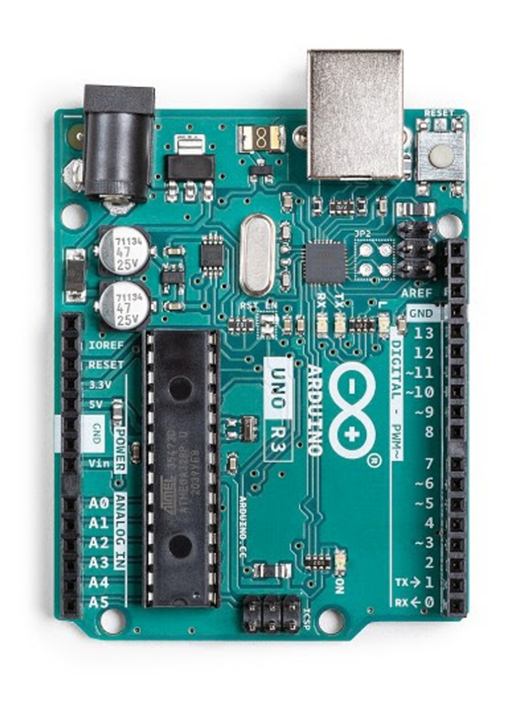
🔹 3. Digital I/O Pins
- Labeled as D0, D1, D2 … up to D13 (Uno)
- Can be configured as INPUT or OUTPUT using
pinMode(). - Reads
HIGH(5V) orLOW(0V).
Example: Turn ON an LED
pinMode(7, OUTPUT);   // Set pin 7 as output
digitalWrite(7, HIGH); // Turn LED ON
delay(1000);          // Wait 1 second
digitalWrite(7, LOW);  // Turn LED OFF
📌 Max current per pin: ~40mA (recommended: 20mA).
🔹 4. PWM Pins (Pulse-Width Modulation)
- Marked with
~symbol (e.g.,~3, ~5, ~6, ~9, ~10, ~11on Uno). - Simulates an analog output (0-255 range) by varying pulse width.
- Used for dimming LEDs, motor speed control.
Example: Fade an LED
analogWrite(9, 128); // Set brightness to ~50% (0-255 range)
📌 PWM Frequency:
- Uno/Nano: ~490Hz (Pins 5, 6: 980Hz)
- Mega: Varies per pin.
🔹 5. Analog Input Pins (A0-A5 on Uno)
- Read analog voltages (0V to 5V).
- Return values between 0-1023 (10-bit resolution).
Example: Read a Potentiometer
int sensorValue = analogRead(A0);
float voltage = sensorValue * (5.0 / 1023.0);
Serial.println(voltage);
📌 Tip: Analog pins can also be used as digital pins (pinMode(A0, OUTPUT);).
🔹 6. Communication Pins
| Protocol | Pins Used | Description |
|---|---|---|
| UART (Serial) | D0 (RX), D1 (TX) | Used for USB communication (connects to PC). |
| I2C (Two-Wire) | A4 (SDA), A5 (SCL) | Connects multiple devices (LCD, sensors). |
| SPI (High-Speed) | D10 (SS), D11 (MOSI), D12 (MISO), D13 (SCK) | Fast communication (SD cards, displays). |
📌 Note:
- Arduino R4 WiFi has dedicated hardware I2C (SDA/SCL) on specific pins.
- Use
Wire.hfor I2C,SPI.hfor SPI, andSerial.begin(9600);for UART.
🔹 7. Special Function Pins
| Pin | Function |
|---|---|
| D2, D3 | External Interrupts (for real-time events). |
| D13 | Built-in LED (on many Arduino boards). |
| RESET | Resets the board when pressed. |
Interrupt Example (Button Press)
attachInterrupt(digitalPinToInterrupt(2), myFunction, FALLING);
📌 Useful for: Sensors, rotary encoders, real-time triggers.
🔹 8. Power Considerations
| Feature | Value |
|---|---|
| Max Pin Current | 40mA (Recommended: 20mA) |
| Max Board Current (5V Regulator) | ~500mA (USB) or ~1A (External 9V Supply) |
| Safe Load for PWM | ~20mA (Use MOSFETs for motors) |
⚠️ Don’t connect high-power devices directly to Arduino! Use relays, transistors, or MOSFETs.
🎯 Summary
- Digital Pins: D0-D13 for ON/OFF signals.
- PWM Pins: ~3, ~5, ~6, ~9, ~10, ~11 simulate analog output.
- Analog Pins: A0-A5 read voltage variations (0-1023).
- Power Pins: 5V, 3.3V, VIN, GND provide power.
- Communication Pins: UART, I2C, SPI for external modules.