An analog-to-digital converter (ADC) reports a ratio to its reference voltage. It does not directly know how many volts your board supply has. A knob powered from that same supply can therefore keep almost the same digital code while its wiper voltage changes. This experiment makes that useful cancellation visible and keeps an assumed five-volt value separate from a measured reference.
Exact parts and the intended measurement
Use an Arduino UNO Rev3 with ATmega328P and Arduino AVR Boards1.8.6, a Bourns 3386P-1-103LF 10 kΩ single-turn trimming potentiometer, a 1 kΩ resistor rated at least 0.125 W, a 100 nF ceramic capacitor and a digital multimeter (DMM). A potentiometer is a resistive track with a movable wiper. Used as a voltage divider, it provides a fraction of the voltage between its end terminals. This trimmer is intended for adjustment, not continuous rotation; its specified rotational life is not an invitation to use it as an endless encoder.
Power the UNO only from its Universal Serial Bus (USB) connector. The experiment’s accepted manually entered supply range is4.50–5.25 V. This is a chosen bench range around the nominal five-volt board, not a new manufacturer rating. At 16 MHz the ordinary ATmega328P voltage/speed operating region matters; do not lower the UNO to an arbitrary battery voltage while keeping its16 MHz clock. Absolute maximum ratings do not define a valid measurement setup.
Share the excitation and reference
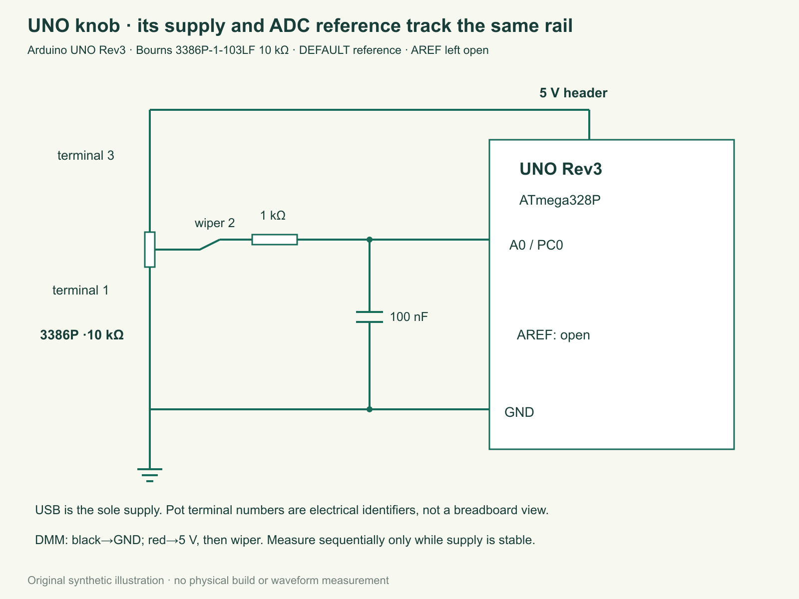
Connect exact potentiometer terminal 3 to the UNO 5 V header and terminal 1 to ground. Terminal2 is the wiper. Pass it through1 kΩ to A0, the PC0 analog input; put100 nF from A0 to ground. The resistor isolates the wiper from the local capacitor and the capacitor supplies short acquisition charge pulses. They do not make an overvoltage input safe. Keep the separate analog-reference pin AREF unconnected and select DEFAULT in software, which uses AVCC, the analog supply reference, on this board.
The numbered potentiometer schematic is an electrical connection guide, not a promise that the pins lie left-to-right in that order when viewed from an arbitrary side. Use the 3386P drawing and marked wiper symbol. Disconnect power before moving wires. Do not feed another supply into5 V while USB is present and do not connect an external reference to AREF for this experiment.
The nominal10 kΩ track has±10% total-resistance tolerance. At the worst central position its equivalent source resistance is one quarter of the track, at most2.75 kΩ for an 11 kΩ track. Adding1 kΩ gives3.75 kΩ, below the datasheet’s approximate10 kΩ source-impedance guidance for ADC acquisition. The conditional resistance–capacitance (RC) time constant is at most3.75 kΩ×100 nF=0.375ms, excluding component tolerances beyond that model. A five-time-constant wait would be1.875ms in this simple model. The 250ms report interval is suitable for a slowly adjusted knob; it is not a measured ADC settling guarantee.
Track dissipation at 5.25 V and 9 kΩ is about 3.1 mW, far below the part’s0.5 W rating at 85 °C. That comparison does not grant a maximum-current rating to the wiper. Here the ADC and meter are high-impedance loads. A disconnected wiper can leave a plausible capacitor voltage, so an ordinary code is not proof that every wire remains connected.
What cancels and what does not
Let alpha be the wiper fraction of the track. In the ideal unloaded model, input voltage equals alpha times supply voltage. With the same supply as ADC reference, the code is approximately the nearest integer to1024×alpha, clipped to0–1023. The factor1024 comes from the converter’s1024 quantization bins. Changes common to both excitation and reference cancel in this ratio. Ground drops, different supplies, loading, offset, noise and reference transients need not cancel.
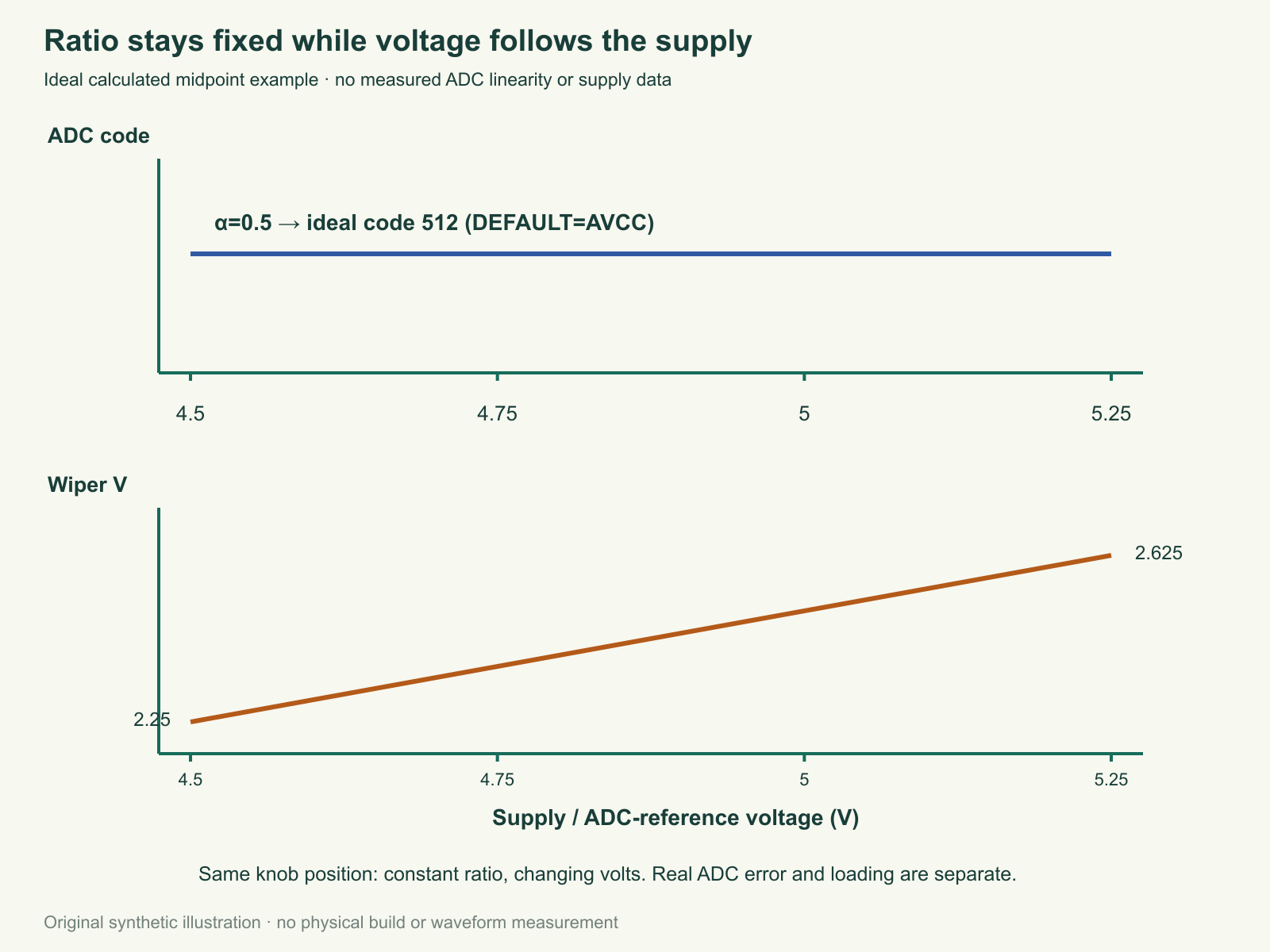
At alpha 0.5 an ideal code is512 both at 4.5 V and 5.25 V, but the actual wiper voltages are2.25 V and 2.625 V. Ratiometric means measuring one quantity as a ratio to another shared quantity. It is useful for position sensors. It is unsuitable evidence that an absolute voltage stayed unchanged.
For code C, the ideal interior bin is[(C−0.5)/1024,(C+0.5)/1024). The program prints that ratio interval and, only with an accepted manual supply entry, an interior-bin center voltage estimate. It does not divide by 1023 and declare both endpoints exact. Real ADC transition errors mean the ideal bin is a teaching model, not a calibrated uncertainty interval. The endpoint bins are clipped by the selected rail-to-rail model. A top or bottom code may also indicate saturation; the program refuses to turn those edge codes into a voltage estimate. No formula can reconstruct an unknown out-of-range input.
Complete program and manual-reference policy
The serial interface accepts exactly V followed by four decimal millivolt digits and a newline. For example, after actually measuring4.950 V, send V4950. This value is an operator statement, not an automatic voltage measurement. An invalid command clears the old reference. An oversized command clears it immediately. No accepted entry means estimated_V remains UNKNOWN while the raw code and ratio bin still print.
A manual entry is permanently invalidated on the first observation more than ten seconds after entry, and only a new accepted command can restore it. A later wrapped timestamp cannot resurrect an already observed expiry. This is an application policy encouraging a recent measurement, not proof that the supply stayed constant. Measure board5 V to ground, then wiper to the same ground sequentially only when the supply is stable. A meter reading at a different moment cannot correct a rapidly changing rail. The program deliberately avoids pretending its own uncalibrated internal reference provides an independently measured supply.
Download full sketch source (ZIP; file: tricky-circuit-batch008-campaigns75-80/code/uno-supply-ratiometric.cpp) · Blank comparison worksheet (ZIP; file: tricky-circuit-batch008-campaigns75-80/code/uno-supply-ratiometric-observations-blank.csv)
/* UNO Rev3 / Arduino AVR Boards1.8.6. Host tests do not execute ADC hardware. */
#include <stdint.h>
struct Reference { uint16_t mV; uint32_t at; bool valid; };
void invalidate(Reference &r){r.valid=false;r.mV=0;}
bool parse_reference(Reference &r,const char *s,uint32_t now){
 invalidate(r);
 if(s[0]!='V')return false;
 unsigned v=0;
 for(int k=1;k<=4;k++){if(s[k]<'0'||s[k]>'9')return false;v=v*10u+(unsigned)(s[k]-'0');}
 if(s[5]!='\0'||v<4500||v>5250)return false;
 r={static_cast<uint16_t>(v),now,true};return true;
}
struct Observation { bool raw_valid,volts_known; uint16_t code; float ratio_low,ratio_high,estimated_V; };
Observation observe(int raw,Reference &r,uint32_t now){
 Observation o={false,false,0,0,0,0};
 if(r.valid&&(uint32_t)(now-r.at)>10000u)invalidate(r);
 if(raw<0||raw>1023)return o;
 o.raw_valid=true;o.code=(uint16_t)raw;o.ratio_low=raw==0 ? 0 : (raw-0.5f)/1024.0f;o.ratio_high=raw==1023 ? 1 : (raw+0.5f)/1024.0f;
 if(raw>0&&raw<1023&&r.valid&&(uint32_t)(now-r.at)<=10000u){o.volts_known=true;o.estimated_V=(raw/1024.0f)*(r.mV/1000.0f);}
 return o;
}
#ifndef HOST_TEST
#include <Arduino.h>
Reference reference={0,0,false};char command[9]={0};uint8_t used=0;bool oversized=false;uint32_t last=0;
void setup(){Serial.begin(115200);analogReference(DEFAULT);pinMode(A0,INPUT);}
void loop(){
 while(Serial.available()){
  char c=(char)Serial.read();
  if(c=='\r')continue;
  if(c=='\n'){
   command[used]='\0';
   if(oversized||!parse_reference(reference,command,millis()))invalidate(reference);
   used=0;oversized=false;
  }else if(used<8&&!oversized){command[used++]=c;}
  else{oversized=true;invalidate(reference);}
 }
 uint32_t now=millis();
 if((uint32_t)(now-last)<250u)return;
 last=now;int raw=analogRead(A0);Observation o=observe(raw,reference,now);
 Serial.print("code=");Serial.print(o.code);Serial.print(" ratio_bin=[");Serial.print(o.ratio_low,6);Serial.print(',');Serial.print(o.ratio_high,6);Serial.print(") estimated_V=");
 if(o.volts_known)Serial.print(o.estimated_V,4);else Serial.print("UNKNOWN");
 Serial.println();
}
#endif
Observe that reference age uses unsigned subtraction so ordinary millis counter wrap is handled within the short policy interval. A hidden full counter wrap with no intervening observation cannot be detected from these timestamps; continuous observations are part of the experiment. A new manual entry restarts only its age; it does not calibrate ADC offset, gain or nonlinearity. Four decimal digits of printed voltage are a display format, not four-decimal measurement accuracy.
Compare ratio with an independent voltage
- Check exact terminal numbers, supply and capacitor connection without power. Use a compatible screwdriver and avoid shorting the trimmer terminals.
- Start near the middle. Record raw code, measured board supply and measured wiper voltage. Enter the measured millivolts and compare the printed interior-bin estimate with the meter, retaining the ideal bin and actual instrument limits.
- Wait beyond ten seconds. Confirm that volts become unknown while the ratio remains available. Send an invalid command and confirm it does not retain an earlier valid reference.
- Keep the trimmer untouched. If using another normal USB source, disconnect the first completely before connecting the second. Measure the new supply and wiper again. A small supply difference may be below your experiment’s resolution; record that instead of inventing a visible change.
- Turn the trimmer slowly toward each end. A saturated endpoint cannot distinguish exact full-scale from a nearby overloaded input. Stay within the board’s own supply rails throughout.
This is distinct from smoothing a noisy knob or timing a multiplexer acquisition: its question is what a count means when the reference itself changes. The electronics lessons cover divider and grounding fundamentals.
Challenge: code 512 repeats on two USB sources. Must the wiper voltage be identical? Answer: no. A shared-supply ratio can remain half scale while both voltages move together. Use an independent, stable-time voltage measurement to investigate absolute volts.
Eight actual portable C++ check groups exercise unknown/valid references, ideal centered bins, endpoint refusal and voltage arithmetic, expiration, invalid raw values, all1024 bins, malformed commands under memory/undefined-behavior sanitizers and wrap/supply-ratio cases. The Arduino adapter is excluded from that host build. No AVR binary, ADC accuracy, physical settling or meter comparison is claimed. The physical log remains empty.
Primary sources
- Exact UNO Rev3 resources
- Arduino AVR core1.8.6 analog implementation
- Microchip ATmega328P complete datasheet
- Bourns exact3386 family sheet
The exact Bourns family sheet, official UNO resources, pinned Arduino core and manufacturer ATmega328P datasheet were checked on20October2026. Their operating conditions and ordinary ADC behavior are separate from absolute stress limits. No separate applicable erratum changing this unmodified A0/DEFAULT topology was located; physical silicon revision and target behavior remain to be checked.
Download the reader files (ZIP): complete source code, the blank observation worksheet and original editable SVG/PNG diagrams for uno-supply-ratiometric are inside tricky-circuit-batch008-campaigns75-80/. The inline program is complete; the download is supplementary.