
A digital number can request an analog voltage without proving that voltage appeared at the connector. Build a three-step source with a Microchip MCP4726A0T-E/CH, measure both sides of a small output resistor, and discover why code resolution, reference accuracy and load regulation are different properties.
A DAC, digital-to-analog converter, turns a numerical code into an analog quantity. This twelve-bit device has 4096 possible codes, from 0 through 4095. Our controller is an original Raspberry Pi Pico with RP2040 and MicroPython 1.26.0. I²C means Inter-Integrated Circuit, the two-wire command bus. GP4/GP5 are numbered general-purpose input/output (GPIO) pins. SDA names serial data and SCL serial clock. The experiment is a small voltage-reference fixture for a voltmeter or a high-resistance input, with no motor, battery charger or actuator connected.
Freeze the complete part number
The specified part is MCP4726A0T-E/CH: A0 selects the fixed bus-address option used here, T denotes tape-and-reel ordering, E is the extended-temperature grade and CH selects the six-lead SOT-23 (small-outline transistor) surface-mount package. A passive SOT-23-to-header adapter makes those small surface-mount leads accessible. Before installing it, verify continuity from every actual chip lead to the adapter’s labelled header pad. Adapter header numbers are not a universal pinout.
The Microchip product page links datasheet DS22272C for the MCP4706/4716/4726 family. Those are eight-, ten- and twelve-bit devices; their data alignment differs. An MCP4725 is also not the same experiment: do not borrow its pin-six function or copy a driver because both names begin with “MCP472.” In this MCP4726, pin six is an external-reference input, not an address strap.
Recommended operation uses a 2.7–5.5 V supply. Here the Pico’s 3.3 V rail supplies the DAC, its digital pullups and its selected voltage reference. Staying within that range does not imply every output code is accurate at every load. The output amplifier needs operating headroom and has offset, gain and loading errors.
Parts and every connection
- Microchip MCP4726A0T-E/CH on a continuity-checked passive adapter; original Raspberry Pi Pico RP2040 running MicroPython 1.26.0.
- Two 4.7 kΩ I²C pullups; 100 Ω output resistor; removable 100 kΩ and 10 kΩ loads. Use 1% resistors, 0.125 W or greater.
- 100 nF ceramic bypass plus 10 µF local bulk capacitor, each rated at least 10 V; observe polarity if the bulk part is polarized.
- Short breadboard wiring, USB cable and a DC voltmeter with known input resistance. DC means direct current; here it describes steady voltage levels. USB, Universal Serial Bus, supplies the Pico and its console.
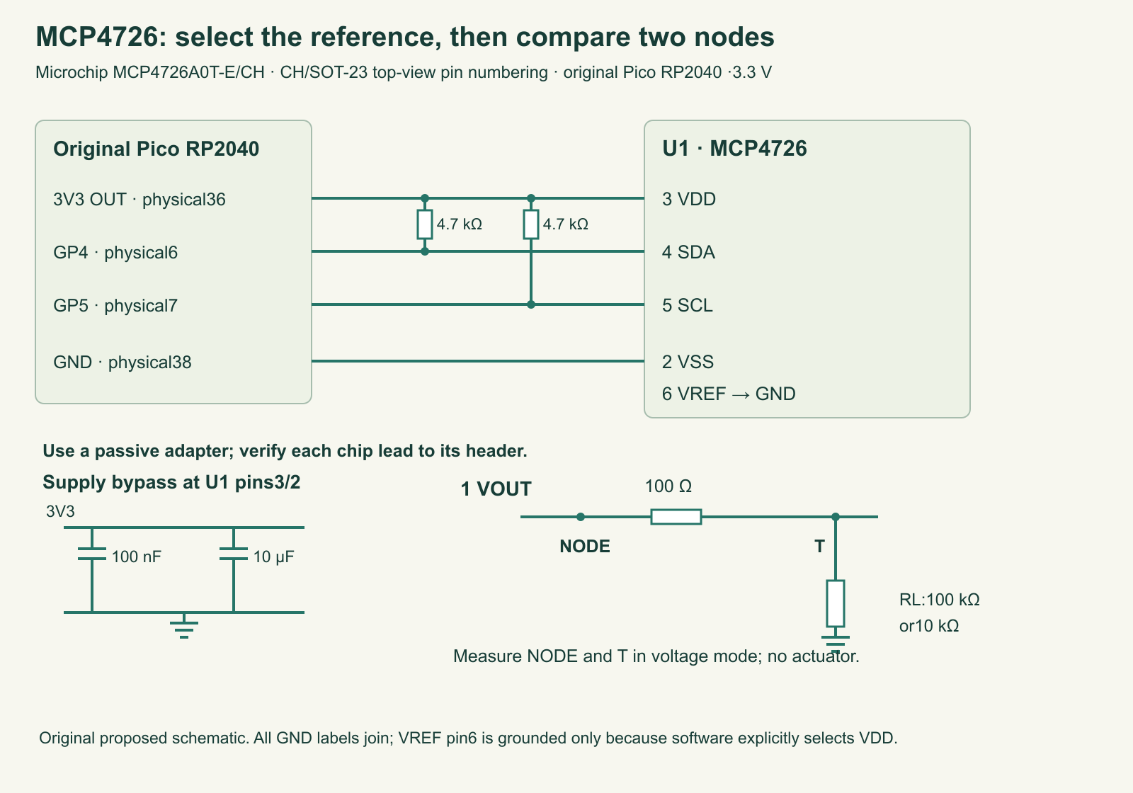
| Exact device pin | Connection and purpose |
|---|---|
| 1 VOUT | DAC node → 100 Ω series resistor → terminal T. Connect the removable load from T to ground; measure pin1 and T separately. |
| 2 VSS | Common ground → Pico GND, physical38. |
| 3 VDD | Pico 3V3 OUT, physical36. Place 100 nF and10 µF from pin3 to pin2, close to the adapter. |
| 4 SDA | Pico GP4, physical6, with4.7 kΩ to3.3 V. Carries bidirectional serial data. |
| 5 SCL | Pico GP5, physical7, with4.7 kΩ to3.3 V. Carries serial clock. |
| 6 VREF | Ground for this VDD-reference-only fixture. The code explicitly selects VDD; the external-reference pin is then disconnected internally. |
I²C, Inter-Integrated Circuit, is the two-wire command interface. Pullups bring released bus lines high; at3.3 V each4.7 kΩ resistor carries about0.70 mA while its line is low. Bypass capacitors provide a local current path and reduce supply disturbance. Keep their ground connection short. The output resistor separates the DAC node from the terminal load; its voltage drop is a deliberate part of this experiment, not an accuracy improvement.
A step size is not a voltage guarantee
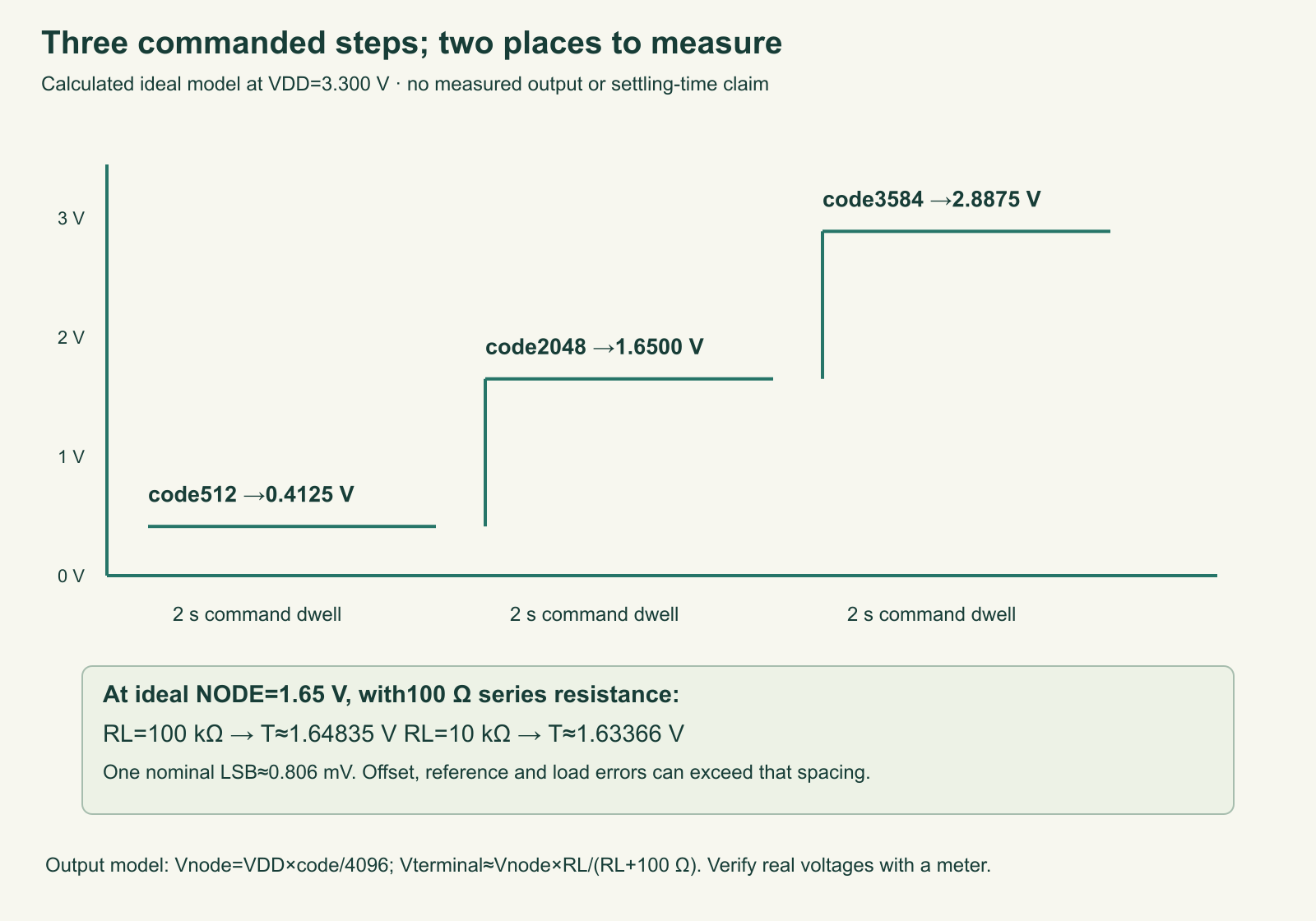
With VDD selected as reference and gain one, the ideal DAC-node voltage is Vnode = VDD × code/4096. At an assumed3.300 V supply, codes512,2048 and3584 request0.4125,1.6500 and2.8875 V. One LSB, least significant bit, corresponds to the ideal adjacent-code spacing3.3/4096 =0.000805664 V, or about0.806 mV. Code4095 is one ideal step below the reference, not exactly VDD.
Measure the actual VDD at pin3 and substitute that number before comparing predicted and observed values. If the supply is3.20 V, midscale predicts1.60 V; if3.40 V, it predicts1.70 V. The DAC cannot remove an error in the reference it is following. Neither twelve-bit addressing nor a command acknowledgement establishes twelve-bit absolute accuracy.
The series resistor creates another predictable effect. For an ideal1.65 V node, a10 kΩ load makes T approximately 1.65 ×10000/(10000+100) =1.63366 V, with about0.163 mA flowing. A100 kΩ load gives1.64835 V. The real DAC output impedance and amplifier error add to this simple model. Its datasheet requires a load greater than5 kΩ for the stated output performance; our fixture uses10 kΩ or more.
Your meter is also a load. A10 MΩ voltage input has little effect compared with10 kΩ, but a low input resistance can alter an unloaded measurement. Write down its specification. Use voltage mode throughout; current is calculated from the measured drop across the known100 Ω resistor. Do not move a meter lead into a current socket for these comparisons.
Select a reference before requesting the steps
Our exact A0 option uses seven-bit address 0x60. The configuration byte 0x80 is the volatile-configuration command: command bits100, reference bits00 selecting VDD, normal-power bits00 and gain bit0. A volatile setting lasts only while the relevant operating state is retained; we do not program nonvolatile memory.
A DAC code then uses two bytes: its upper four bits, followed by its lower eight bits. The upper command/power bits remain zero, so the fast write changes the volatile DAC value and selects normal power. For example,2048 is 0x0800 and sends bytes08 00. This is not the same alignment as the device’s readback format.
EEPROM, electrically erasable programmable read-only memory, stores settings that may be recalled when power starts. We never issue its write-all-memory command in the loop. A previously used device can recall an old output before our program selects a new one; even changing the reference can move that output. Attach only the specified passive test load and meter.
Complete MicroPython program
Save the listing under a simple importable name such as dac_steps.py on the Pico and run import dac_steps; dac_steps.main(). The downloadable source has a descriptive filename; rename it on the board if importing it. The console reports acknowledged commands and explicitly leaves measured_output_V absent. The default3.3 V model is labelled nominal; it is not an automatic supply measurement.
Download full code (mcp4726-voltage-staircase.py inside ZIP) · Blank voltage worksheet (mcp4726-voltage-staircase-observations-blank.csv inside ZIP)
"""Original Pico RP2040 / MicroPython 1.26.0; MCP4726A0T-E/CH only.
An acknowledged command is not a measured voltage. No EEPROM write command.
"""
ADDRESS = 0x60
STEPS = (512, 2048, 3584)


def pack_code(code):
    if type(code) is not int or not 0 <= code <= 4095:
        raise ValueError('DAC code must be an integer 0..4095')
    return bytes([(code >> 8) & 0x0f, code & 0xff])


def ideal_voltage(code, reference_v):
    pack_code(code)
    if not 2.7 <= reference_v <= 5.5:
        raise ValueError('reference model outside operating supply')
    return reference_v * code / 4096.0


def loaded_terminal(node_v, load_ohm, series_ohm=100.0):
    if load_ohm < 10000 or series_ohm < 0:
        raise ValueError('this fixture requires load >=10k and nonnegative series R')
    return node_v * load_ohm / (load_ohm + series_ohm)


class MCP4726:
    def __init__(self, bus):
        self.bus = bus

    def transfer(self, data):
        if self.bus.writeto(ADDRESS, data) != len(data):
            raise OSError('short acknowledgement; output state unknown')

    def configure(self):
        # C2:C0=100; VREF1:0=00 (VDD); PD1:0=00; G=0.
        self.transfer(b'\x80')

    def write(self, code):
        self.transfer(pack_code(code))  # 00xx header: volatile DAC, PD=00.


def staircase(dac, sleep_ms, emit=print, cycles=3, reference_model_v=3.3):
    if type(cycles) is not int or not 1 <= cycles <= 100:
        raise ValueError('cycles must be 1..100')
    # Validate the arithmetic model before changing the output.
    predictions = [ideal_voltage(code, reference_model_v) for code in STEPS]
    last_acknowledged = None
    try:
        dac.configure()
        for _ in range(cycles):
            for code, predicted in zip(STEPS, predictions):
                dac.write(code)
                last_acknowledged = code
                emit({'state': 'COMMAND_ACKNOWLEDGED', 'requested_code': code,
                      'nominal_unloaded_V': predicted,
                      'reference_model_V': reference_model_v,
                      'measured_output_V': None})
                sleep_ms(2000)
        dac.write(0)
        emit({'state': 'ZERO_COMMAND_ACKNOWLEDGED', 'measured_output_V': None})
        return True
    except OSError as exc:
        emit({'state': 'BUS_ERROR_OUTPUT_UNKNOWN',
              'last_acknowledged_code': last_acknowledged,
              'measured_output_V': None, 'error': str(exc)})
        return False


def main():
    from machine import Pin, SoftI2C
    from time import sleep_ms
    bus = SoftI2C(sda=Pin(4), scl=Pin(5), freq=100000, timeout=20000)
    dac = MCP4726(bus)
    try:
        staircase(dac, sleep_ms)
    except KeyboardInterrupt:
        try:
            dac.write(0)
            print('Stopped; zero command acknowledged, verify with a voltmeter.')
        except OSError:
            print('Stopped; output UNKNOWN. Disconnect power before rewiring.')


if __name__ == '__main__':
    main()
Run the comparison in controlled stages
- With power disconnected, verify the chip marking, adapter mapping, both grounds and all six pins. Fit the capacitors and pullups. Leave the test load disconnected. Use the Pico’s USB supply only; do not inject another positive supply at its3V3 pin.
- Power up and measure VDD at the DAC. Run the program and record each code, pin1 voltage and T voltage. Each requested level is held for two seconds and the three-level sequence repeats. Repeat the run if more time is needed; a meter’s display update can lag the command.
- Disconnect power and add100 kΩ from T to ground. Repeat the same sequence, then repeat with10 kΩ. Keep meter, leads and range unchanged. Compare measured pin1-to-T drop with current calculated as that drop/100 Ω.
- Compare the measured change at pin1 with the change at T. A larger terminal drop can coexist with a relatively steady DAC node. A node that itself moves reveals additional loading, reference or amplifier behavior; the simple external divider equation did not include those effects.
- For a bus-fault trial, power off, remove SDA and restart. Expect BUS_ERROR_OUTPUT_UNKNOWN. An earlier successful command is only history. Restore wiring with power off and restart. Do not assume a disconnected bus makes the output zero.
- Stop a normal run. The program requests zero and reports whether that command was acknowledged. Measure the node before calling it zero. A bus failure ends further writes and keeps the output unknown; this design has no independent hardware shutdown.
No waveform fidelity, slew rate or arbitrary cable stability is established by a steady meter reading. The100 Ω resistor is not a universal compensation network. Use short leads and no intentional output capacitor. The datasheet discusses reduced linearity near the ends of the code range; our three interior codes help study loading without pretending to characterize every code.
What the local tests establish
The host tests execute the actual packing, driver and staircase functions. They exhaustively encode all4096 legal values; reject negative, overflowing and noninteger codes; check the three nominal voltages, supply changes and external load equations; inject short acknowledgements and failures at configuration, every step and final-zero requests. They verify that no later command is sent after failure and that no output is reported as measured. They do not test an I²C electrical waveform, calibrate the amplifier or build a MicroPython firmware binary.
Challenge: will code2048 still mean1.65 V if VDD falls to3.0 V?
No. With VDD as reference, ideal midscale falls to1.50 V. A separate accurate reference could change the design, but it needs a different pin-six connection, configuration, headroom analysis and source. Renaming the constant in the program does not create that hardware reference.
Primary sources and next experiments
- Microchip DS22272C: SOT-23 pin table, reference selection, transfer equation, address options and volatile command formats.
- MCP4726 current product/documentation page. A targeted official-site review found no separate device erratum; that is not proof none can exist for a particular lot.
- Original Pico documentation and MicroPython1.26.0 I²C reference.
Continue with a voltage divider under load and the interactive lessons. Record real measurements in the blank sheet before making a calibration claim or connecting this fixture to another project.
Download the complete experiment sources (ZIP): full programs, full-size PNG and editable SVG diagrams, and blank worksheets in separate experiment folders. The complete program remains inline above.