A pulse train can disappear while a microcontroller keeps running. A retriggerable one-shot turns each qualifying edge into a fresh hardware deadline: the output stays HIGH while edges arrive within the chosen timing window, then falls when the window expires. Build a small SN74AHC123AN experiment that distinguishes an omitted pulse, a stuck HIGH wire and an intentional reset.
Scope: this is an unmeasured low-voltage bench design and a test procedure. The supplied Python model and host tests check logic assumptions and commanded sequences. They do not qualify the power rail, measure the chip, run the Pico firmware or establish a safety watchdog. An oscilloscope is needed to qualify the supply and observe millisecond gaps.
What the output actually means
A monostable has one resting state. A qualifying input edge starts a temporary output pulse; a retriggerable monostable lets another suitably spaced edge extend that pulse. The SN74AHC123AN contains two such channels. We use channel 1, a resistor and a capacitor to make a nominal 10 millisecond (ms) window. The Pico requests rising edges approximately every 6 ms. Omitting one requested edge creates a nominal 12 ms interval, long enough for the ideal 10 ms output to expire.
Q HIGH means that a qualifying trigger occurred recently enough for this timing circuit. It does not prove that a sensor reading is correct, an application made progress, a communication packet arrived intact or a motor is safe. Q LOW also occurs during clear and before the first trigger. Its complementary output, Q̅, therefore cannot by itself distinguish “missed pulse” from “not started” or “held in reset.” Keep the input and reset traces alongside the output when interpreting a capture.
The electronics course provides the resistor, capacitor and digital-level foundations for this experiment. A software progress watchdog answers a different question: whether specified work completed. Here the useful result is learning exactly which electrical edges refresh a hardware interval.
Exact parts and instruments
| Item | Selection and job |
|---|---|
| U1 | Texas Instruments SN74AHC123AN, N / 16-pin plastic dual in-line package (PDIP). Use the AHC123A variant and current SCLS352I, revised January 2025; an HC, HCT, AHCT or single-gate part is not an assumed substitute. |
| Stimulus board | Original Raspberry Pi Pico with RP2040; MicroPython 1.26.0. General-purpose input/output (GPIO) GP2 commands B; GP3 commands active-LOW clear. GPIO numbers and physical header numbers differ. |
| R1 and C1 | 100 kilohms (kΩ), ±1% metal-film timing resistor; WIMA MKS2C031001A00JSSD, 100 nanofarads (nF), ±5%, nonpolar polyester film, 63 volts direct current (VDC), 5 mm lead spacing. J/S/SD specify tolerance, bulk packaging and lead length, not a different timing principle. |
| R2 and R3 | Two 10 kΩ, ±1% pull-down resistors. They define B LOW and clear LOW while the Pico pins are inputs; they cannot override a GPIO actively driving HIGH. |
| C2 | 100 nF, at least 10 V, X7R ceramic bypass capacitor directly between U1 pins 16 and 8. Its job is local supply decoupling, separate from C1’s timing job. |
| Instruments | Oscilloscope with high-impedance probes for supply ramp, B, clear and Q. A 3.3 V compatible logic analyzer can supplement timing captures after the supply is qualified. Do not enable a scope’s 50 Ω input termination on these logic outputs. |
Use one common 3.3 V domain, nominally the Pico’s 3V3_OUT rail. The supply qualification below is a prerequisite: this article does not assert that an arbitrary Pico, cable or power cycle meets U1’s ramp conditions. Keep the timing network close to U1 and away from switching conductors. The functional drawing is a net diagram, not a breadboard hole map.
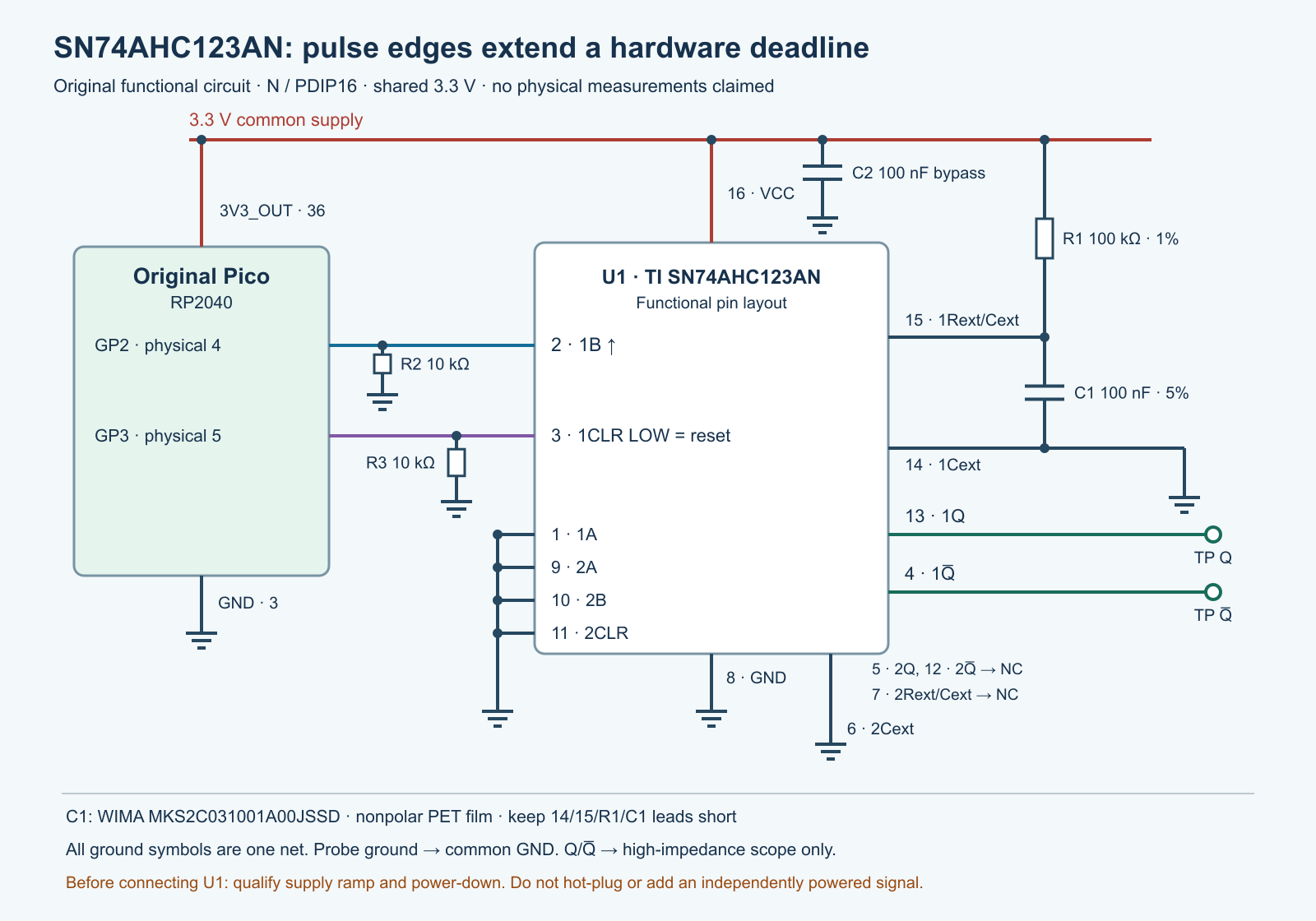
tricky-circuit-batch009-campaigns81-86/images/sn74ahc123a-missing-pulse.svg).Trace every connection before power
Disconnect Universal Serial Bus (USB) power and all external sources before wiring. With the package viewed from above and its notch upward, pin 1 is upper left, numbering runs down the left side to 8, then up the right side from 9 to 16. Locate the package marking and check the manufacturer’s top view; do not count from the underside.
| U1 terminal | Exact connection | Purpose |
|---|---|---|
| 16, VCC; 8, GND | Pico 3V3_OUT physical 36 to 16; Pico GND physical 3 to 8. C2 directly across 16–8. | Shared 3.3 V power and reference. |
| 1, 1A | Common GND. | Allows rising edges on B to trigger. |
| 2, 1B | Pico GP2, physical 4. R2 = 10 kΩ from this same node to GND. | Rising-edge trigger input. |
| 3, 1CLR | Pico GP3, physical 5. R3 = 10 kΩ from this same node to GND. | LOW overrides the timing pulse; HIGH permits operation. |
| 15, 1Rext/Cext | R1’s lower end and C1’s first terminal. R1’s other end goes to VCC. | Timing resistor/capacitor junction. |
| 14, 1Cext | C1’s second terminal and common GND. | Capacitor return. Grounding Cext is permitted in TI’s SCLA014 Figure 2 guidance. |
| 13, 1Q; 4, 1Q̅ | Separate probe tips/test points. Every probe ground goes to common GND. | Observe the active pulse and its complement, without a significant output load. |
| 9, 2A; 10, 2B; 11, 2CLR; 6, 2Cext | Common GND. | Unused channel held cleared with defined inputs and capacitor-return potential. |
| 7, 2Rext/Cext; 5, 2Q; 12, 2Q̅ | No connection (NC): leave each separate and insulated. | No timing network or output load on the unused half. |
The capacitor connects between 15 and 14; it is not a resistor from 15 to ground, and pin 14 is not an output. Grounding pin 14 also grounds this fixture’s capacitor return. The bypass capacitor goes across the supply, not across the timing resistor. A filled dot marks a junction in the drawing; do not merge two nets just because they pass near each other.
Operating conditions and a supply qualification hold
The current TI operating table allows VCC from 2 to 5.5 V. This fixture stays in the 3.3 V ±0.3 V timing regime and uses R1 well above the stated 1 kΩ minimum for VCC greater than 3 V. The older SCLA014 note mentions a 250 Ω minimum; that older value does not override the current datasheet. Recommended logic-output loading at 3.3 V is ±4 milliamperes (mA). The ±25 mA output and ±50 mA supply/ground figures are absolute stress boundaries, not target currents. Our outputs connect only to high-impedance instruments.
Each asserted GPIO feeds its 10 kΩ pull-down: nominal current is 3.3/10000 = 0.33 mA. With 3.6 V and a 9.9 kΩ resistor it is about 0.364 mA, plus the IC input leakage. Do not connect 5 V signaling, independently powered instruments that drive these nodes or a 5 V logic board to this fixture. Shared ground does not make unlike supply levels compatible.
Supply hold: Rev I’s recommended-condition table places the value 1 ms/V for Δt/ΔVCC in the MIN column. We preserve that printed condition; we do not silently reinterpret it as a maximum rise time or claim that a normal Pico startup meets it. Before fitting U1, scope the intended rail with a representative load and review its rise against the exact current document. If the meaning or compliance is uncertain, stop and obtain TI clarification or qualify a different supply arrangement before continuing. Record the rail trace and setup, not just “3.3 V” from a meter.
Power-down needs attention too. C1 stores roughly ½CV² = 0.545 microjoules (µJ) at 3.3 V. Stored energy is small, but a fast discharge can still produce a short current spike. TI’s application paragraph uses a 30 mA discharge calculation and contains “pin 2 or pin 14,” which conflicts with the package’s Cext pin map, 6/14. Do not use that sentence as wiring instructions or permission to exceed the separate 20 mA clamp-current stress ratings. Its 3.3 V × 100 nF / 30 mA ≈ 11 microseconds (µs) is only application guidance, not verified protection of this assembly. Measure and qualify the real rail collapse; no external clamp network or power-down compliance has been tested here.
Establish B LOW and clear LOW before switching off, and remove power from the common assembly together. Do not power U1 separately, hot-plug a timing capacitor or hold an input HIGH while its supply disappears. The pull-downs define disconnected inputs, not an enforced shutdown. If either commanded LOW fails or the supply tests are unresolved, stop the experiment and investigate rather than treating the model as approval to continue.
Calculate a window, then measure it
For the selected 100 nF capacitor, TI’s application equation uses K = 1.0. In International System of Units (SI) form the nominal relation is tW ≈ KRC. This is not the 0.45RC approximation commonly copied from a different logic family. Here V means volts, s seconds, Ω ohms and F farads. Convert units consistently: a microfarad (µF) is 1000 nF; 100 nF is 0.1 µF, not 100 µF.
Nominal RC window = 1 × 100000 Ω × 100e-9 F = 0.010 s = 10 ms
RC-only low corner  = 0.99 × 0.95 × 10 ms = 9.405 ms
RC-only high corner = 1.01 × 1.05 × 10 ms = 10.605 ms
Approximate retrigger separation = 0.30 × tW
At the high RC corner: 0.30 × 10.605 ms = 3.1815 ms
Requested edge interval P = 6 ms; one omitted edge gives 2P = 12 ms
Those corners include only the initial resistor and capacitor tolerances. They omit device multiplier variation, temperature, supply sensitivity, leakage, parasitic capacitance and aging. They are not guaranteed minimum/maximum chip pulse widths. WIMA’s capacitance tolerance does not establish a lifetime timing accuracy. TI’s roughly 0.30tW minimum-retrigger guidance is also application information, not a complete worst-case guarantee for every RC choice.
Within this conditional calculation, 6 ms exceeds 3.1815 ms and is below 9.405 ms, while 12 ms exceeds 10.605 ms. Thus an ideal window bridges ordinary intervals but expires after an omission. In the 10 ms model an edge at 18 ms sets expiry at 28 ms; if the next expected edge at 24 ms is omitted, Q is LOW from 28 to the recovery edge at 30 ms. A short dark blink on an LED would be a poor instrument for this gap, which is why the fixture uses scope test points.
On the real bench, first measure isolated pulse width W, actual edge intervals P and their variation. Establish a retrigger spacing that works repeatably for this setup. For a useful missing-one-edge observation, ordinary intervals must stay below the shortest observed window and above the qualified retrigger separation; an omitted interval must exceed the longest observed window. A software pause can cause a genuine electrical gap even though your intended pulse list has no omission. Record that distinction. Do not operate near the boundary and describe an intermittent result as guaranteed detection.
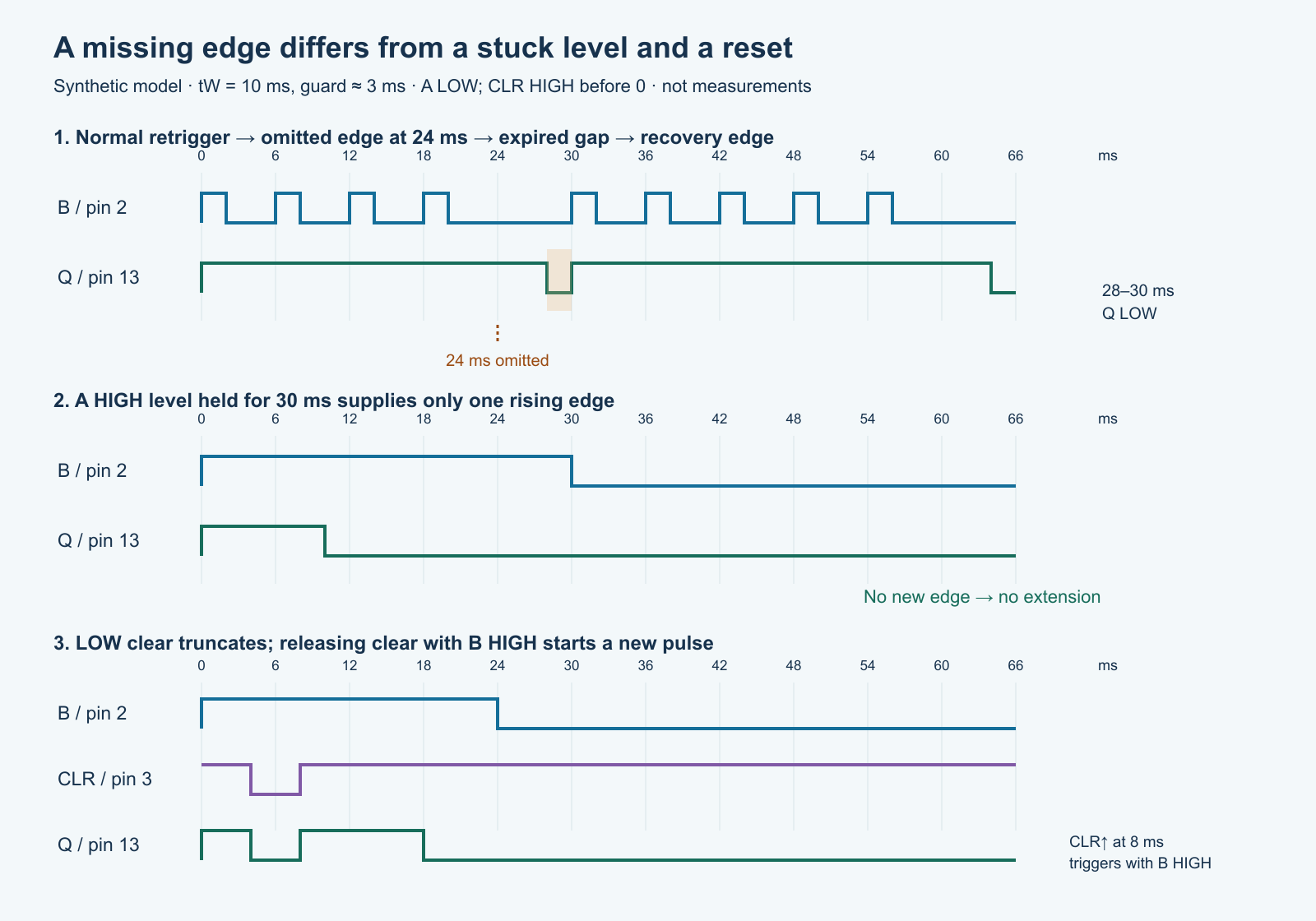
tricky-circuit-batch009-campaigns81-86/images/sn74ahc123a-missing-pulse-logic.svg).Reset ordering is part of the circuit
With A LOW, a rising B edge triggers if clear is HIGH. A falling A edge can also trigger while B is HIGH. A third, easily missed condition is clear rising while A is LOW and B is HIGH: releasing reset can itself start a pulse. Holding B HIGH does not continuously retrigger; it provides one rising edge and then a steady level. Changing a gating level does not necessarily truncate an already active pulse; pulling clear LOW does.
The supplied program first creates clear as an output LOW, then B as an output LOW, waits a requested 50 ms, and releases clear while B remains LOW. It waits a further requested 1 ms before producing the first B edge. That 1 ms is a conservative bench sequencing delay, not a newly invented datasheet recovery-time specification. During normal startup there should be no deliberately generated clear-release pulse. TI describes a glitch-free power-up state under its operating conditions; we still use explicit clear to establish a known test sequence and do not extend that statement to an unqualified power rail.
Complete stimulus and conditional model
Save the complete Python program (ZIP; file: tricky-circuit-batch009-campaigns81-86/code/sn74ahc123a-missing-pulse.py) on the original Pico as sn74ahc123a-missing-pulse.py, then run it once from the MicroPython read–evaluate–print loop (REPL). It requests eight normal periods, an omission, a long gap, a stuck-HIGH interval and an early clear. It never samples Q, and no console line is an output-voltage observation. MicroPython’s delays can take longer than requested because of interrupts, interpreter work or console output. Capture actual timing; the labels describe the requested stimulus.
After saving the file in the Pico filesystem and completing the hardware prerequisites, enter these commands at the REPL. Finish the with block with a blank line before entering exec. The explicit main name runs the finite sequence once; this does not install an automatic startup script.
with open("sn74ahc123a-missing-pulse.py") as f:
    stimulus_source = f.read()

exec(stimulus_source, {"__name__": "__main__"})
RetriggerModel is a separate teaching model. It takes relative integer microseconds, not a raw wrapping tick counter. Start it with clear LOW. Too-close retriggers, simultaneous qualifying edges and an edge exactly at the assumed expiry produce sticky UNKNOWN until clear LOW establishes a state again. That deliberately conservative policy does not claim which analog outcome silicon will choose. Calling a model “UNKNOWN” is more useful than asserting that every rapid edge was accepted or ignored.
"""SN74AHC123AN bench stimulus plus a conditional, discrete-time model.

Original Pico / MicroPython 1.26.0: GP2 -> 1B, GP3 -> active-LOW 1CLR.
This file never reads Q. Model results and pin commands are NOT measurements.
The model assumes a selected pulse width and approximate retrigger guard; it
returns UNKNOWN for unsupported edge spacing instead of inventing silicon data.
"""
import math


def rc_budget(resistance_ohms=100000, capacitance_nf=100):
    """Fixture-only RC arithmetic, not a guaranteed device timing range."""
    for value in (resistance_ohms, capacitance_nf):
        if type(value) not in (int, float) or not math.isfinite(value):
            raise ValueError("finite numeric component value required")
    if not 99000 <= resistance_ohms <= 101000:
        raise ValueError("R must be within this 100 kOhm, 1% fixture")
    if not 95 <= capacitance_nf <= 105:
        raise ValueError("C must be within this 100 nF, 5% fixture")
    width_us = resistance_ohms * capacitance_nf / 1000.0
    return {"rc_width_us": width_us,
            "approx_retrigger_us": 0.30 * width_us,
            "not_a_device_guarantee": True}


class RetriggerModel:
    """Ideal function-table model with conservative UNKNOWN boundaries.

    Relative integer microseconds only; not a wrapping hardware tick counter.
    A LOW clear establishes a known state. An unsupported too-close retrigger,
    simultaneous qualifying edges, or a trigger exactly at expiry stays UNKNOWN
    until another LOW clear. Propagation delay and analog dynamics are omitted.
    """
    def __init__(self, width_us=10000, guard_us=3000):
        if (type(width_us) is not int or type(guard_us) is not int
                or not 0 < guard_us < width_us):
            raise ValueError("require integer 0 < guard < width")
        self.width = width_us
        self.guard = guard_us
        self.now = None
        self.levels = None
        self.deadline = None
        self.last_trigger = None
        self.known = False

    def apply(self, now_us, a, b, clear):
        if type(now_us) is not int or now_us < 0:
            raise ValueError("relative time must be a nonnegative integer")
        if self.now is not None and now_us < self.now:
            raise ValueError("relative time must not go backwards")
        if any(type(x) is not int or x not in (0, 1) for x in (a, b, clear)):
            raise ValueError("logic levels must be integer 0 or 1")
        previous = self.levels
        self.now, self.levels = now_us, (a, b, clear)
        if not clear:
            self.known, self.deadline, self.last_trigger = True, None, None
            return self.snapshot()
        if previous is None or not self.known:
            return self.snapshot()
        old_a, old_b, old_clear = previous
        events = int(old_b == 0 and b == 1 and a == 0)
        events += int(old_a == 1 and a == 0 and b == 1)
        events += int(old_clear == 0 and clear == 1 and a == 0 and b == 1)
        if events:
            too_close = (self.last_trigger is not None
                         and now_us - self.last_trigger < self.guard)
            at_expiry = self.deadline is not None and now_us == self.deadline
            if events > 1 or too_close or at_expiry:
                self.known = False
                self.deadline = None
            else:
                self.deadline = now_us + self.width
                self.last_trigger = now_us
        elif self.deadline is not None and now_us >= self.deadline:
            self.deadline = None
        return self.snapshot()

    def snapshot(self):
        q = None if not self.known else int(self.deadline is not None)
        return {"q": q, "q_bar": None if q is None else 1 - q,
                "state": "UNKNOWN" if q is None else ("ACTIVE" if q else "IDLE"),
                "deadline_us": self.deadline, "model_only": True}


def run_patterns(make_output, delay_us, emit=print, report=None):
    """Command a finite demonstration; make_output(gpio, initial) is injected.

    delay_us attempts a minimum delay. Calls/interrupts add unknown time. Capture
    actual B/CLR/Q with an instrument. report records successful GPIO commands,
    not measured pin voltage. A failed cleanup leaves that command UNKNOWN.
    """
    if report is None:
        report = {}
    report.update({"clear_low_command": None, "b_low_command": None,
                   "completed": False})
    clear_pin = b_pin = None
    try:
        # Assert reset before obtaining/operating the trigger pin.
        clear_pin = make_output(3, 0)
        report["clear_low_command"] = True
        b_pin = make_output(2, 0)
        report["b_low_command"] = True
        emit("STIMULUS ONLY: 6 ms target period; Q is not sampled")
        delay_us(50000)
        clear_pin.value(1)  # B is LOW: release does not intentionally trigger.
        report["clear_low_command"] = False
        delay_us(1000)     # Deliberate bench settling delay, not a specified t_rec.

        def pulse():
            b_pin.value(1)
            report["b_low_command"] = False
            delay_us(2000)
            b_pin.value(0)
            report["b_low_command"] = True
            delay_us(4000)

        emit("NORMAL: eight requested 6 ms pulse periods")
        for _ in range(8):
            pulse()
        emit("OMIT ONE: extra 6 ms LOW; last-to-next target interval 12 ms")
        delay_us(6000)
        pulse()
        emit("LONG GAP: extra 30 ms LOW")
        delay_us(30000)
        pulse()
        emit("STUCK HIGH: hold B HIGH 30 ms; only its first edge can trigger")
        b_pin.value(1)
        report["b_low_command"] = False
        delay_us(30000)
        b_pin.value(0)
        report["b_low_command"] = True
        delay_us(30000)
        emit("CLEAR: truncate a new pulse after a requested 2 ms")
        b_pin.value(1)
        report["b_low_command"] = False
        delay_us(2000)
        clear_pin.value(0)
        report["clear_low_command"] = True
        b_pin.value(0)
        report["b_low_command"] = True
        delay_us(50000)
        report["completed"] = True
    finally:
        # Try both independently even if one write (or an interruption) fails.
        for pin, key in ((clear_pin, "clear_low_command"),
                         (b_pin, "b_low_command")):
            report[key] = None
            if pin is not None:
                try:
                    pin.value(0)
                    report[key] = True
                except BaseException:
                    pass
    return report


def main():
    from machine import Pin
    from time import sleep_us
    report = {}
    try:
        run_patterns(lambda gpio, initial: Pin(gpio, Pin.OUT, value=initial),
                     sleep_us, report=report)
    finally:
        print("Cleanup command acknowledgements, not voltage measurements:", report)


if __name__ == "__main__":
    main()
The finite pattern function attempts clear LOW and B LOW independently in finally, including when the first console message fails or an interruption occurs. A returned True means a pin command completed; it does not prove the physical voltage. None means cleanup was unavailable or failed. If pin construction fails after an internal side effect, the program might not have an object with which to undo it. Disconnect and inspect the hardware; do not rely on a successful cleanup message as an independent protection circuit.
A reproducible bench sequence
- With U1 removed, review the supply qualification hold. Measure the intended common rail’s rise and fall with the intended power setup and representative load. Resolve the Rev I conditions and current paths before fitting U1. Keep instrument ground attached only to common GND.
- Remove power, fit U1, and continuity-check every table entry, the timing capacitor identity and package orientation. Confirm unused timing pin 7 is open and unused inputs are fixed. A disconnected breadboard rail segment is not a common supply.
- After qualified power-up, observe clear and B during program startup. B must be LOW when clear rises. Q should remain in the cleared/resting state until the first qualifying B edge; capture all three signals if the result differs.
- Capture an isolated B edge followed by a long LOW gap. Measure Q’s pulse width from that capture. Record supply, actual R/C values if measured, temperature, probe settings and elapsed time since power-up. Leave unmeasured fields blank.
- Run the finite program and measure the actual ordinary rising-edge intervals. Compare the omission’s interval and resulting Q LOW gap with the conditional RC calculation. If printing adds a gap, label it as observed stimulus delay; do not silently substitute the requested 6 ms.
- Check stuck HIGH and stuck LOW separately. HIGH supplies one initial rising edge; LOW supplies none. Q should eventually rest after a qualified isolated trigger. A stuck level is not a healthy heartbeat.
- Check early clear: when clear goes LOW during an active pulse, Q should fall early. To explore the reset-release trap, first use the host model. A later physical test must deliberately establish B HIGH under clear LOW, then release clear under scope observation; label that pulse “reset release,” not “received heartbeat.”
- For a boundary experiment, change spacing in a copy only after saving baseline captures. Move gradually toward the approximate retrigger region and record outcomes as observations, not universal limits. Restore the baseline code after the experiment. On interruption, verify both LOW levels before removing common power.
Use the blank observation worksheet (ZIP; file: tricky-circuit-batch009-campaigns81-86/code/sn74ahc123a-missing-pulse-observations-blank.csv). There are no sample measurements to copy. The local author suite exercises the actual supplied model and stimulus with injected pin, delay and output failures; host execution does not build or run firmware and cannot validate pulse width, ramp behavior or a physical missing-pulse detector.
Challenge: why did reset produce a heartbeat?
You see Q rise immediately when clear is released, before the first intended Pico pulse. A is grounded, B is already HIGH, and clear had been LOW. Is the timing capacitor necessarily wrong? What happens if B stays HIGH afterward?
Show the answer
No. Clear’s rising edge is itself a documented trigger when A is LOW and B is HIGH. Establish B LOW before releasing clear to avoid that intentional startup condition. Keeping B HIGH afterward creates no further rising edges, so the resulting pulse eventually expires. A longer RC window would hide the symptom for longer; it would not fix the sequencing mistake. Check the actual B/clear traces before blaming the capacitor.
Primary references and boundaries
- TI SCLS352I, SNx4AHC123A, January 2025: exact pin map, operating and stress limits, timing tests, function table and application caveats. Application guidance is distinct from guaranteed specification tables.
- TI exact SN74AHC123AN ordering page: N / PDIP16 identity, ACTIVE lifecycle on review and −40 to +85 °C part range. Lifecycle does not promise stock availability.
- TI SCLA014, Designing With the SN74AHC123A and SN74AHCT123A: older circuit and timing background, including permitted grounded Cext. Its older resistor minimum and dimensionally unclear frequency wording do not override current conditions or dimensional analysis.
- WIMA MKS 2, March 2026: 100 nF / 63 V row and J/S/SD part-number completion, film construction and capacitance tolerance.
- Raspberry Pi original Pico pinout: 3V3_OUT, GND and GPIO-to-header mapping.
- MicroPython 1.26.0 Pin and time: initial output values, pin operations and the limits of requested delays.
The current TI product documentation and an official-domain errata search were checked; no separate applicable errata document was found in that bounded search. That is not proof none exists. Supply qualification, actual width/retrigger measurements and target execution remain outstanding. This circuit is a teaching indicator, not a substitute for a qualified supervisory or safety system.
Download the reader files (ZIP): complete source code, the blank observation worksheet and original editable SVG/PNG diagrams for sn74ahc123a-missing-pulse are inside tricky-circuit-batch009-campaigns81-86/. All inline programs are complete; the download is supplementary.