A tiny chip, two lights and one button are enough to build a reaction game. Press and release the button to arm it, wait for green, then press again. The green light reports your result in roughly 100-millisecond steps. This project teaches inputs, timing and a state machine: a program that changes what it does according to its current stage.
Target: a bare ATtiny85 in an eight-pin dual in-line package (DIP), running at 1 MHz from its factory clock configuration. This wiring is not for a Digispark board. A microcontroller is a chip that runs a program and controls electrical inputs and outputs; it does not need Linux.
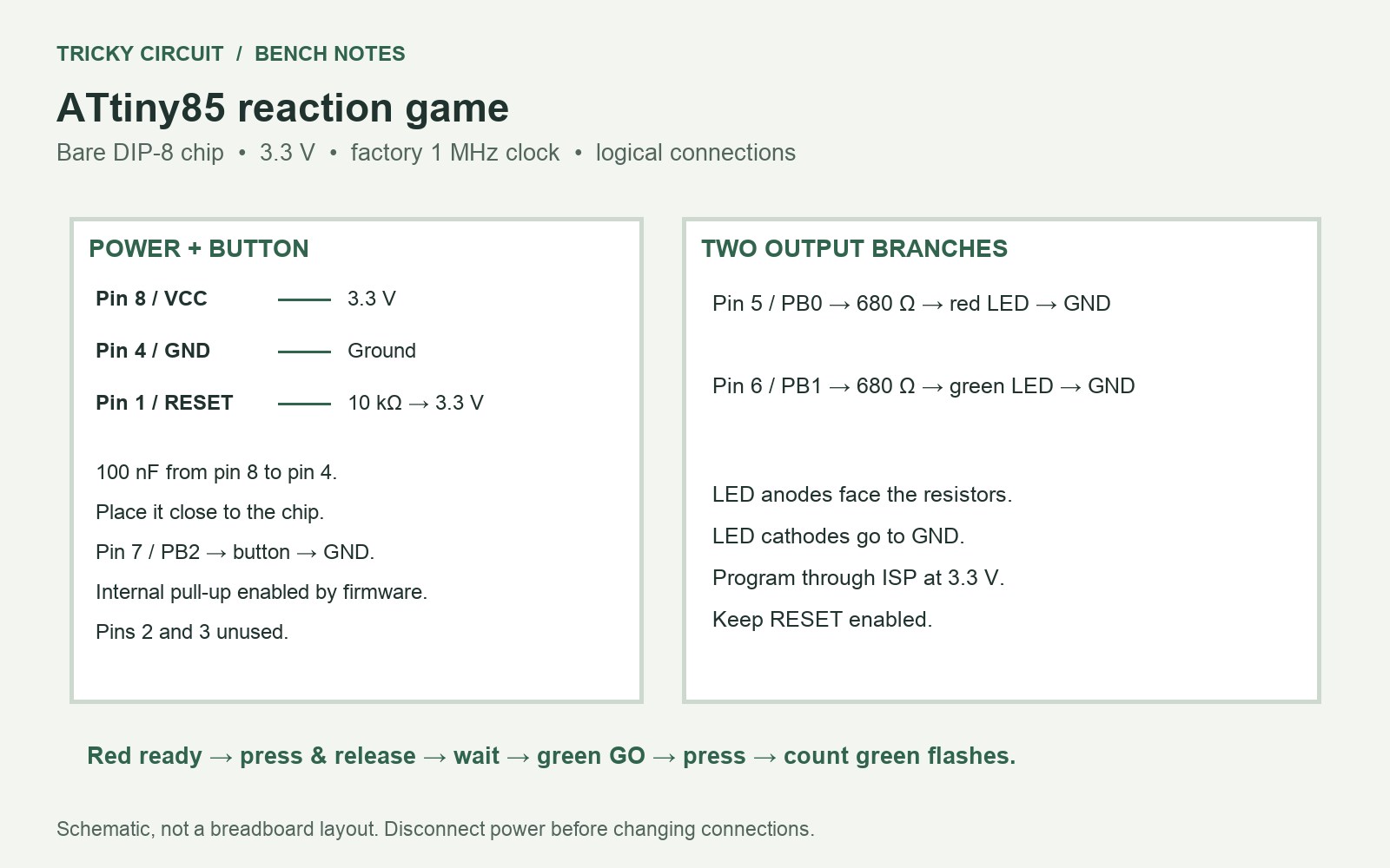
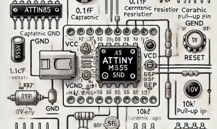
Parts and connections
- ATtiny85 DIP-8, breadboard and wires.
- Regulated 3.3 V supply; a programmer that supports this target voltage and its slow clock.
- One red and one green LED (light-emitting diode), two 680 Ω resistors.
- One normally open pushbutton, a 10 kΩ resistor and a 100 nF ceramic capacitor.
Pin numbers below refer to the chip package. PB0, PB1 and PB2 are the manufacturer’s port-bit names. Check the notch, pin-one mark and datasheet before inserting the chip.
| Connection | Purpose |
|---|---|
| Pin 8 → 3.3 V; pin 4 → ground | Power and common reference. |
| 100 nF between pins 8 and 4, close to the chip | Decoupling: supplies brief local current changes. |
| Pin 1 / RESET → 10 kΩ → 3.3 V | Keeps reset inactive during normal operation. |
| Pin 5 / PB0 → 680 Ω → red LED anode; cathode → ground | Ready and error indication. |
| Pin 6 / PB1 → 680 Ω → green LED anode; cathode → ground | Go signal and result. |
| Pin 7 / PB2 → button → ground | Active-low input, using the chip’s internal pull-up. |
A pull-up holds the input high when the button is open; pressing connects it to ground. With a 2.0 V red LED, the ideal current is (3.3 − 2.0) / 680 ≈ 1.9 mA. Actual current depends on the LED and output voltage. Never omit either LED resistor.
Build and program
- Disconnect power, build the power connections and decoupling first, then add the lights and button.
- Use an AVR toolchain containing avr-gcc, avr-libc and avr-objcopy. AVR is the microcontroller family; these tools turn C source into a firmware image.
- Save the full source below as
reaction.cand build it with the commands shown. - Write
reaction.hexusing your programmer’s documented ATtiny85 procedure. ISP means in-system programming: programming the chip through its reset, clock and data pins. Use a slow programming clock appropriate to a 1 MHz target, such as 125 kHz. - Keep the factory internal 8 MHz oscillator divided by eight, giving a 1 MHz processor clock. Do not disable RESET or change fuses blindly. Previously used chips may have different clock settings.
- Power-cycle after programming. The red light should stay on. Disconnect the programmer if it affects the button or lights.
avr-gcc -mmcu=attiny85 -DF_CPU=1000000UL -Os -std=gnu11 -Wall -Wextra reaction.c -o reaction.elf
avr-objcopy -O ihex -R .eeprom reaction.elf reaction.hex
The programming interface shares PB0 and PB1 with the LEDs. If programming is unreliable, disconnect those LED branches while programming. Avoid powering the circuit simultaneously from two supplies.
Full firmware
/* Tricky Circuit: bare ATtiny85, factory 1 MHz clock, 3.3 V. */
#include <avr/io.h>
#include <avr/interrupt.h>
#include <util/atomic.h>
#include <stdint.h>
#if F_CPU != 1000000UL
#error This timer configuration requires a 1 MHz CPU clock
#endif
#define RED _BV(PB0)
#define GREEN _BV(PB1)
#define BUTTON _BV(PB2)
static volatile uint32_t ticks;
ISR(TIM0_COMPA_vect) { ++ticks; }
static uint32_t millis(void) {
    uint32_t copy;
    ATOMIC_BLOCK(ATOMIC_RESTORESTATE) { copy = ticks; }
    return copy;
}
static void leds(uint8_t value) { PORTB = BUTTON | value; }
int main(void) {
    DDRB = RED | GREEN;
    leds(RED);
    TCCR0A = _BV(WGM01);             /* CTC: clear timer on compare. */
    TCCR0B = _BV(CS01);              /* Divide clock by 8. */
    OCR0A = 124;                     /* 125 counts = 1 ms at 1 MHz. */
    TIMSK |= _BV(OCIE0A);
    sei();
    enum { IDLE, RELEASE, WAIT, GO, RESULT, ERROR } state = IDLE;
    uint8_t stable = 1, candidate = 1, flashes = 0;
    uint32_t changed = 0, started = 0, wait_ms = 0, rng = 0x6d2b79f5UL;
    for (;;) {
        uint32_t now = millis();
        uint8_t raw = (PINB & BUTTON) != 0, pressed = 0;
        if (raw != candidate) { candidate = raw; changed = now; }
        if (candidate != stable && (uint32_t)(now - changed) >= 10) {
            stable = candidate;
            pressed = !stable;
        }
        switch (state) {
        case IDLE:
            if (pressed) { leds(0); state = RELEASE; }
            break;
        case RELEASE:
            if (stable) {
                rng ^= now; if (!rng) rng = 1;
                rng ^= rng << 13; rng ^= rng >> 17; rng ^= rng << 5;
                wait_ms = 1000 + rng % 3001;
                started = now; state = WAIT;
            }
            break;
        case WAIT:
            if (pressed) { started = now; state = ERROR; }
            else if ((uint32_t)(now - started) >= wait_ms) {
                leds(GREEN); started = now; state = GO;
            }
            break;
        case GO:
            if (pressed) {
                uint32_t elapsed = now - started;
                flashes = (elapsed + 50) / 100;
                if (!flashes) flashes = 1;
                if (flashes > 50) flashes = 50;
                leds(0); started = now; state = RESULT;
            } else if ((uint32_t)(now - started) >= 5000) {
                started = now; state = ERROR;
            }
            break;
        case RESULT: {
            uint32_t elapsed = now - started;
            if (elapsed < 800) leds(0);
            else if (elapsed - 800 < (uint32_t)flashes * 300)
                leds(((elapsed - 800) % 300 < 150) ? GREEN : 0);
            else { leds(RED); state = IDLE; }
            break;
        }
        case ERROR:
            if ((uint32_t)(now - started) < 900)
                leds(((now - started) % 300 < 150) ? RED : 0);
            else { leds(RED); state = IDLE; }
            break;
        }
    }
}
Play, then inspect the timing
Press and release to start. Both lights go out for a variable one-to-four-second interval. When green appears, press immediately. After a short pause, count green flashes: three flashes mean approximately 300 ms. Early presses or waiting five seconds produce three red flashes. Release before starting another round.
The hardware timer counts 125 steps at 125,000 steps per second: 1 MHz / 8 / 125 = 1,000 timer events per second. An interrupt briefly runs a small function that increments the millisecond counter. The main loop handles the game without long blocking delays. The variable wait is pseudorandom and seeded by button timing; it is suitable for a game, not security.
Mechanical contacts bounce. The program requires an input to remain unchanged for 10 ms before accepting it. That adds delay, and the internal oscillator is not a precision time reference. Treat this as an approximate game, not a calibrated reaction measurement. Display rounding also limits resolution.
If it does not behave as expected
Eight-times-fast timing usually means an 8 MHz clock was used with firmware built for 1 MHz. A permanently pressed input suggests the wrong button legs or a short to ground. No light suggests power, LED polarity or chip orientation; check these before changing software.
Challenge: why is there a separate release state?
It prevents the press used to arm the game from being treated as the reaction. The waiting interval starts only after a stable release.
Related: practice voltage, current and switches in the interactive lab. Technical reference: Microchip ATtiny25/45/85 datasheet, including clock, package pinout and Timer/Counter0 sections.