A useful smart-home project starts with a clear rule. Our room node turns on a small indicator when the room is dark and movement has been detected recently. It also measures room temperature independently. You will build three different sensor interfaces, then see exactly which readings control the output.
Build: a classic ESP32-DevKitC V4 with an ESP32-WROOM-32/32E module, running MicroPython 1.26. The output is a low-power LED (light-emitting diode) representing a nightlight. This is a tabletop prototype, not a mains-light controller or a security alarm.
What each part does
| Part | Signal | Job in the room |
|---|---|---|
| PIR motion module | Digital: low or high | Reports changes in infrared radiation associated with movement. |
| LDR and resistor divider | Analog: a changing voltage | Indicates whether the room is relatively bright or dark. |
| DS18B20 | Digital temperature messages | Reports temperature near the sensor. |
| ESP32 program | Decision | Combines darkness and recent motion; prints all sensor states. |
| LED with series resistor | Output | Shows when the nightlight rule is true. |
PIR means passive infrared. “Passive” means it senses incoming radiation rather than sending out a measuring beam. It detects movement-related changes; a person sitting still may stop triggering it. LDR means light-dependent resistor: its resistance generally falls as illumination increases. Neither sensor identifies a person.
Parts and complete wiring
- The specified ESP32 board, USB data cable, breadboard and jumpers.
- A PIR module specified for 5 V supply and a 3.3 V digital output, such as the type documented in Adafruit’s PIR guide. Verify the actual module’s pin labels and output voltage.
- One LDR, two 10 kΩ resistors, one 4.7 kΩ resistor and one 680 Ω resistor.
- DS18B20 temperature sensor and a red or yellow indicator LED.
USB means Universal Serial Bus; it powers the development board and carries the programming connection. GPIO means general-purpose input/output. The pin numbers in this table are GPIO labels, not connector positions or names such as D1.
| Connection | Reason |
|---|---|
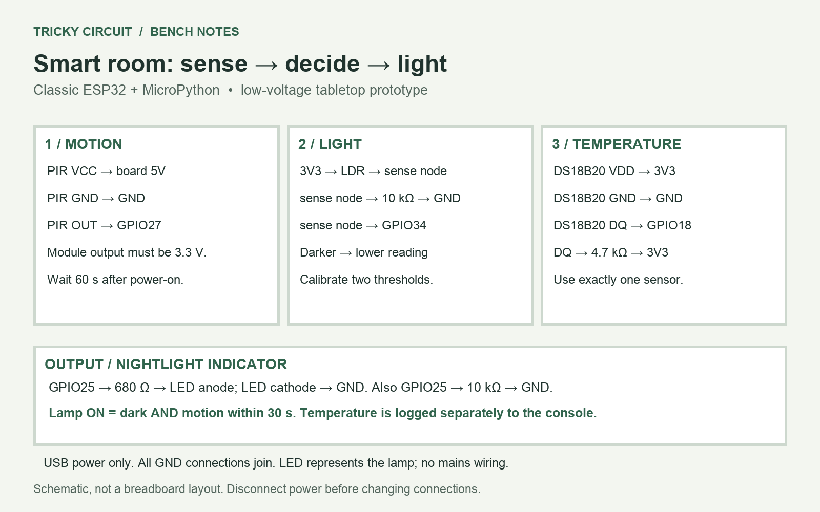
| PIR VCC → board 5V; PIR GND → board GND; PIR OUT → GPIO27 | Power the specified module and read its 3.3 V output. Supply the board only by USB. |
| 3V3 → LDR → sense node → 10 kΩ → GND; sense node → GPIO34 | Brighter light lowers LDR resistance and raises the sensed voltage. |
| DS18B20 VDD → 3V3; GND → GND; DQ → GPIO18 | Three-wire temperature interface. |
| 4.7 kΩ between DQ and 3V3 | Pull-up for the 1-Wire data bus. |
| GPIO25 → 680 Ω → LED anode; LED cathode → GND | Current-limited nightlight indicator. |
| 10 kΩ between GPIO25 and GND | Keeps the indicator off while the pin is not yet configured at startup. |
All grounds connect together. Check the DS18B20 package view instead of assuming probe wire colours. The PIR’s 5 V supply does not imply a 5 V-safe ESP32 input: only a documented 3.3 V output connects directly. Keep the temperature sensor away from the warm ESP32 board.
The light divider and its limitations
If the LDR happens to measure 10 kΩ, the sense voltage is 3.3 × 10 / (10 + 10) = 1.65 V. If it rises to 100 kΩ in darkness, the voltage becomes about 0.30 V. These are illustrative resistance values; your LDR and room will differ.
The ADC, or analog-to-digital converter, converts input voltage into a number. We use GPIO34 on ADC1 and a raw scale from 0 to 65,535. This is a relative light reading, not calibrated lux, the unit of illuminance. The classic ESP32 ADC is nonlinear and can saturate near the top of this 3.3 V divider’s range even with the selected attenuation. That is acceptable for this threshold experiment; do not treat raw values as accurate voltages.
Install, calibrate and run
- Install the official MicroPython build for your classic ESP32 using its getting-started guide. Save the program below as
main.pyon the board. - Run it and leave the PIR still for the first 60 seconds. The LED stays off during this settling interval.
- Read the
light=values in the serial console under normal lighting and with the LDR covered. Covering this wiring arrangement should reduce the value. - Choose
DARK_ONabove your stable dark readings, then choose a higherBRIGHT_OFFbelow your stable bright readings. The starting values 18,000 and 26,000 are examples to adjust, not universal light levels. - Restart, wait for settling, cover the LDR and move across the PIR’s field of view. The LED should turn on. Uncover the LDR: it should turn off when the reading exceeds the bright threshold.
- In darkness, stop moving. The LED stays on for 30 seconds after the PIR last reports high. The module’s own output-hold time adds to the time since your physical movement.
Full MicroPython program
"""Classic ESP32, MicroPython 1.26: motion + light + room temperature."""
# Calibrate these from printed raw ADC readings in your room.
DARK_ON = 18000
BRIGHT_OFF = 26000
HOLD_MS = 30000

def update_dark(raw, was_dark):
    if raw < DARK_ON:
        return True
    if raw > BRIGHT_OFF:
        return False
    return was_dark

def main():
    from machine import Pin, ADC
    import time
    import onewire
    import ds18x20
    light = ADC(Pin(34), atten=ADC.ATTN_11DB)
    motion = Pin(27, Pin.IN)
    lamp = Pin(25, Pin.OUT, value=0)
    thermometer = ds18x20.DS18X20(onewire.OneWire(Pin(18)))
    roms = [rom for rom in thermometer.scan() if rom[0] == 0x28]
    sensor = roms[0] if len(roms) == 1 else None
    print("Warming PIR for 60 seconds; lamp stays off.")
    time.sleep(60)
    dark = False
    last_motion = None
    conversion_started = None
    next_temperature = time.ticks_ms()
    last_report = time.ticks_ms()
    temperature = None
    temperature_status = "waiting" if sensor else "need exactly one DS18B20; restart after fixing"
    try:
        while True:
            now = time.ticks_ms()
            raw = light.read_u16()
            dark = update_dark(raw, dark)
            moving = bool(motion.value())
            if moving:
                last_motion = now
            recent = last_motion is not None and time.ticks_diff(now, last_motion) < HOLD_MS
            lamp.value(dark and recent)
            if sensor is not None:
                try:
                    if conversion_started is None and time.ticks_diff(now, next_temperature) >= 0:
                        thermometer.convert_temp()
                        conversion_started = now
                    elif conversion_started is not None and time.ticks_diff(now, conversion_started) >= 800:
                        temperature = thermometer.read_temp(sensor)
                        if temperature is None or not -55 <= temperature <= 125:
                            raise ValueError("invalid temperature")
                        temperature_status = "ok"
                        conversion_started = None
                        next_temperature = time.ticks_add(now, 4200)
                except (OSError, ValueError):
                    temperature = None
                    temperature_status = "sensor error"
                    conversion_started = None
                    next_temperature = time.ticks_add(now, 5000)
            if time.ticks_diff(now, last_report) >= 1000:
                print("light=", raw, "dark=", dark, "motion=", moving,
                      "lamp=", lamp.value(), "C=", temperature, temperature_status)
                last_report = now
            time.sleep_ms(50)
    finally:
        lamp.off()

if __name__ == "__main__":
    main()
Why the decision is stable
Two light thresholds create hysteresis: the boundary for entering darkness differs from the boundary for leaving it. A reading between the thresholds keeps the previous dark/bright state. That avoids rapid flickering when a value jitters around one boundary. Keep the indicator’s light away from the LDR so it does not create a feedback loop.
The nightlight rule is dark AND recent_motion. Temperature is displayed but does not control this light. The program starts a temperature conversion and checks the result after 800 ms while continuing to process motion. It does not freeze the light logic for the entire conversion time.
A missing or failed temperature sensor prints a status and an unknown value; it does not become a fictitious zero. Exactly one DS18B20 is expected. Fix a missing or ambiguous sensor and restart. A sensor failing after startup is retried. A disconnected LDR cannot reliably be distinguished from extreme darkness by this simple divider, which is one reason this prototype is not a safety system.
Test the purpose, not just the wires
Try four cases: bright plus movement, bright without movement, dark plus movement, and dark after the hold period expires. Only dark plus recent movement should light the indicator. Test temperature separately by gently holding the sensor package; it should change gradually while the lighting rule remains the same.
Challenge: why does one threshold flicker more easily?
If the threshold is 22,000 and readings alternate between 21,950 and 22,050, the decision changes every time. With separate 18,000 and 26,000 thresholds, those readings retain the previous state.
This is the first room module for a larger smart-home series. A leak detector can add another sensor input, while a Raspberry Pi can later collect room logs. Those extensions need their own wiring and failure-handling lessons.
Related: why divider loading matters and interactive circuit lessons. References: MicroPython ESP32 ADC and 1-Wire interfaces, ESP32 firmware setup, Adafruit PIR module guide, and DS18B20 datasheet.