Build a handheld indicator that shows how strongly an ESP32 hears your Wi-Fi network. Green, yellow and red lights make it easy to compare a desk, hallway and distant room. The lesson is about measuring a radio signal and handling missing data honestly.
Target board: classic ESP32-DevKitC V4 with an ESP32-WROOM-32 or WROOM-32E module. This pin list is not interchangeable with ESP32-C3 or ESP32-S3 boards. GPIO means general-purpose input/output: a programmable electrical pin. The board uses 3.3 V logic and is powered through its USB (Universal Serial Bus) connector.
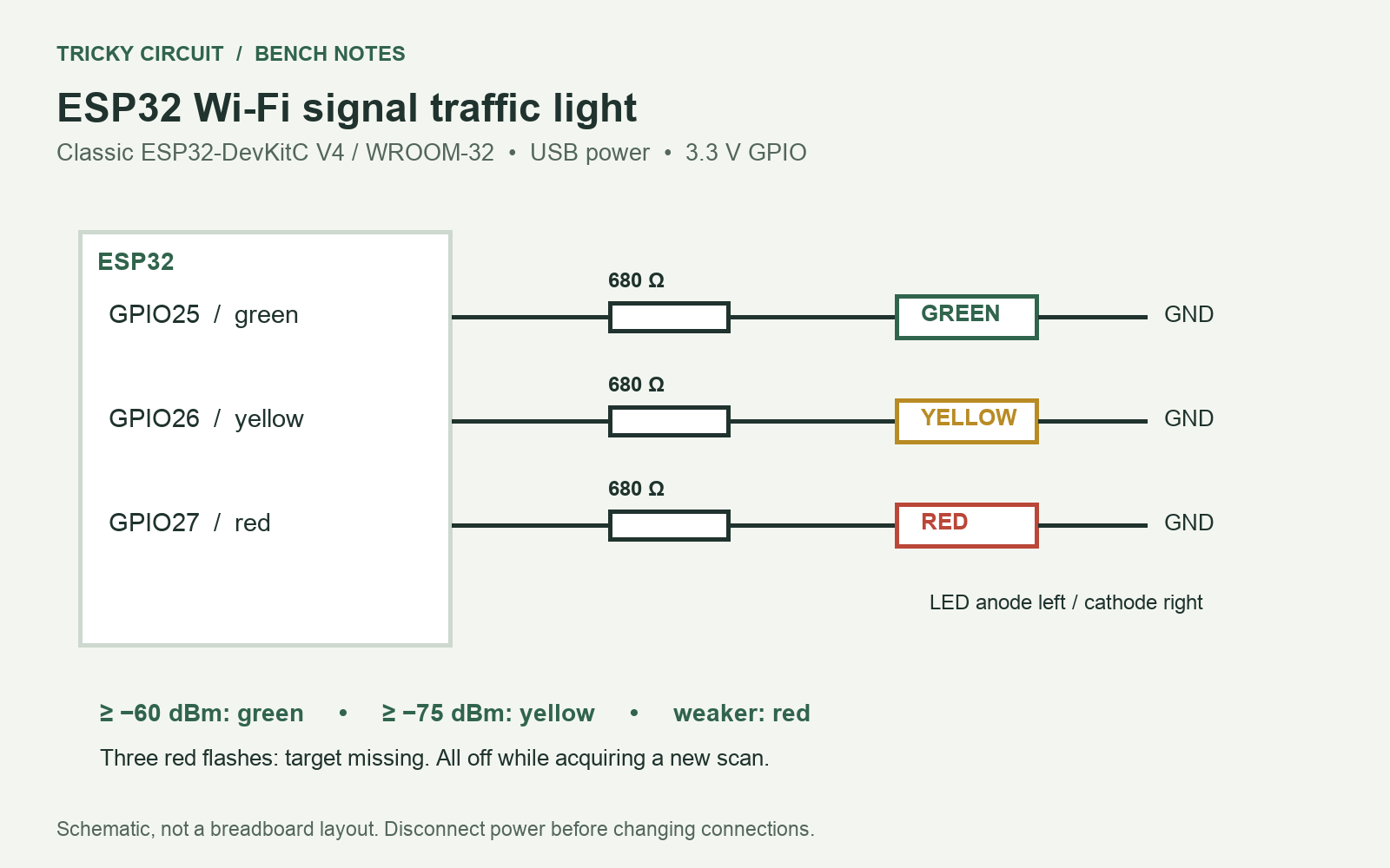
What you need
- The specified ESP32 board, USB data cable and computer.
- Red, yellow and green LEDs (light-emitting diodes), each with its own 680 Ω resistor.
- Breadboard and jumper wires.
Connect GPIO25 through 680 Ω to the green LED’s anode; connect its cathode to ground. Repeat with GPIO26 for yellow and GPIO27 for red. All three ground connections join a board GND pin. Do not connect any signal pin to the board’s 5 V supply.
For a nominal 2.0 V LED, ideal current is (3.3 − 2.0) / 680 ≈ 1.9 mA. Green devices vary in forward voltage, so brightness may differ. Use ordinary indicator LEDs that are visible at a few milliamps.
Install and upload
- In the Arduino integrated development environment (IDE), install the official esp32 by Espressif Systems board package using its documented installation procedure.
- Select the matching classic ESP32 board, commonly ESP32 Dev Module, and the correct serial port.
- Create a sketch named
wifi_signal, paste the full program below, and changeYOUR_NETWORKto the exact visible name of your own network. The name is its SSID, or service set identifier. - Upload, then open Serial Monitor at 115200 baud, the communication speed used by the program.
- Keep the board at one location for several scans. Move it without touching its antenna area, and compare readings with the same orientation.
No password is needed. The sketch scans for the network’s announcements; it does not join the network or send results to a server. It performs a passive scan and waits ten seconds after each completed scan. A whole cycle therefore takes longer than ten seconds.
Full sketch
#include <WiFi.h>
// Classic ESP32-DevKitC V4 / ESP32-WROOM-32. No network password needed.
const char *TARGET_SSID = "YOUR_NETWORK";
const int GREEN = 25, YELLOW = 26, RED = 27;
void lights(int selected) {
  digitalWrite(GREEN, selected == GREEN);
  digitalWrite(YELLOW, selected == YELLOW);
  digitalWrite(RED, selected == RED);
}
void setup() {
  Serial.begin(115200);
  pinMode(GREEN, OUTPUT); pinMode(YELLOW, OUTPUT); pinMode(RED, OUTPUT);
  lights(-1);
  WiFi.mode(WIFI_STA);
  WiFi.disconnect();
}
void loop() {
  lights(-1); // Do not display the previous reading during a new scan.
  int count = WiFi.scanNetworks(false, false, true); // Blocking, passive scan.
  bool found = false;
  int strongest = -127;
  for (int i = 0; i < count; ++i) {
    if (WiFi.SSID(i) == TARGET_SSID) {
      int rssi = WiFi.RSSI(i);
      if (!found || rssi > strongest) strongest = rssi;
      found = true;
    }
  }
  WiFi.scanDelete();
  if (count < 0) {
    Serial.println("Scan failed; LEDs off. Retrying after 10 seconds.");
  } else if (!found) {
    Serial.println("Target network not seen in this scan.");
    for (int i = 0; i < 3; ++i) {
      lights(RED); delay(150); lights(-1); delay(150);
    }
  } else {
    Serial.printf("Target signal: %d dBm\n", strongest);
    lights(strongest >= -60 ? GREEN : strongest >= -75 ? YELLOW : RED);
  }
  delay(10000);
}
Interpret the lights
| Display | Meaning in this experiment |
|---|---|
| Green | Signal at least −60 dBm. |
| Yellow | Signal from −75 dBm up to, but not including, −60 dBm. |
| Red, steady | Network found below −75 dBm. |
| Three red flashes, then off | Target network not seen in this scan. |
| All off during scanning | A fresh result is being acquired; a scan error is also reported in Serial Monitor. |
RSSI means received signal strength indication. Here it is reported in dBm, decibels relative to one milliwatt. A value closer to zero is stronger: −55 dBm is stronger than −75 dBm. These thresholds are our display choices, not guarantees of a particular connection speed.
A radio reading is not an internet speed test. Interference, congestion and the router’s internet connection can affect performance independently. The original ESP32 supports 2.4 GHz Wi-Fi; a network available only at 5 GHz will not appear. A hidden network name can also prevent this name-based match.
A useful experiment
Write down five readings at each of three locations and compare their middle values. Then rotate the board at one location. Reflections and antenna direction can change readings even when distance stays the same. If a mesh system has several access points with the same name, this sketch displays the strongest matching signal found in that scan.
Switch off your access point briefly, if doing so will not interrupt anyone else’s work. The indicator should stop showing a stale green result and show the missing-network pattern on a later scan. This is a simple example of treating “unknown” differently from “weak.”
Challenge: what should the display do at −60 and −75 dBm?
Exactly −60 dBm is green; exactly −75 dBm is yellow. A reading of −76 dBm is red. Boundary conditions matter when translating a threshold into code.
Related: understand LED current through a resistor. References: Espressif Wi-Fi API, official Arduino board-package installation, and DevKitC V4 pinout and power options.