A panel can have eight switches even when a controller has only a few spare pins. Reading them one after another directly creates an awkward question: did that combination ever exist at one instant? This experiment uses a parallel-input register to hold a pattern, then reads the stored bits slowly enough to inspect the order. The useful result is an input snapshot, with a clearly defined capture boundary and honest limits around changing contacts.
This is a locally checked design for an original Raspberry Pi Pico with RP2040, MicroPython 1.26.0, and a Texas Instruments SN74HC165N in the 16-pin N plastic dual-inline package (PDIP). Power and console communication use Universal Serial Bus (USB). There is no physical build, measured timing or target execution in the evidence. The complete sampler was exercised on a host against an ideal logical model.
What each part contributes
| Part | Quantity | Purpose |
|---|---|---|
| TI SN74HC165N | 1 | Loads eight parallel logic levels and shifts their stored pattern to QH. |
| Original Pico RP2040 | 1 | Controls load and clock and prints the captured byte over USB. |
| 10 kΩ resistors, 1% or 5% | 11 | Eight input pull-ups and three control defaults prevent floating inputs. |
| Normally-open buttons or switches | 8 | Pull a selected input to ground when closed. |
| 100 nF ceramic capacitor | 1 | Local bypass between integrated circuit (IC) supply and ground; short connections matter. |
The eight input pull-ups make a released contact read as one. Closing a contact conducts through its resistor: I = 3.3 V / 10 kΩ = 0.33 mA nominal. Eight closed contacts use about 2.64 mA in these branches, in addition to the boards’ consumption. One closed branch dissipates about 1.09 mW in its resistor. These are nominal calculations, not measured current or a complete Pico supply budget. A pull-up defines a logic default; it does not debounce a mechanical switch.
Wire by pin function, then verify power
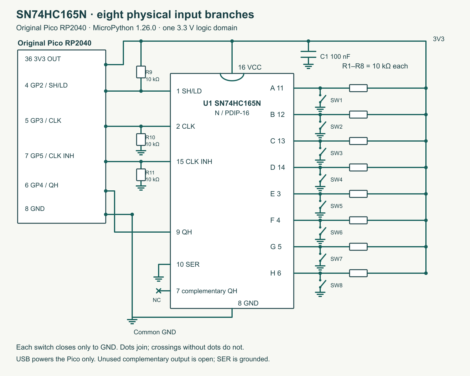
Power the Pico from USB and the IC from the Pico’s 3V3 OUT, physical pin 36. Join grounds. This entire experiment uses 3.3 V logic; do not insert a 5 V switch signal. Locate the PDIP notch before counting pins. The complementary output at pin 7 is deliberately unused; it is an output and can remain open. Serial input pin 10 is tied to ground so bits shifted into the tail have a defined zero value.
| SN74HC165N function / pin | Connection | Why |
|---|---|---|
| VCC 16 / GND 8 | 3.3 V / common GND; 100 nF across 16 and 8 | Short local supply path. |
| SH/LD 1 | Pico GP2, physical 4; 10 kΩ to 3.3 V | Low loads the parallel inputs; high permits the stored pattern to shift. |
| CLK 2 | GP3, physical 5; 10 kΩ to GND | Rising edges advance the stored pattern when enabled. |
| QH 9 | GP4, physical 6 | Read H before issuing the first shift edge. |
| CLK INH 15 | GP5, physical 7; 10 kΩ to GND | Held low during ordinary operation. |
| A/B/C/D | Pins 11/12/13/14 | One separate button and 10 kΩ pull-up per input. |
| E/F/G/H | Pins 3/4/5/6 | The remaining four separate input branches. |
| SER 10 / complementary QH 7 | GND / unconnected | Defined inserted bits / unused output. |
With power disconnected, inspect each input branch and ground continuity. Then power up and measure the actual supply before installing any external signal. The selected HC device’s recommended supply range is 2–6 V; its 7 V absolute maximum is not an operating target. Related LS, HCT, automotive or differently packaged parts require their own electrical and pin checks. A similar name does not establish a safe substitute.
A snapshot is not eight independent reads
While SH/LD is low, loading is transparent: changes at A–H can change the parallel contents. Raising SH/LD ends that loading phase. The byte subsequently shifted out belongs to that boundary, subject to the device’s input timing requirements. A contact moving near that boundary can be ambiguous. The register neither synchronizes an arbitrary asynchronous signal nor turns switch bounce into one clean event.
After loading, QH already presents H. The sampler reads that bit first, then issues a rising and falling clock pair before each following read. Eight reads therefore need seven shift pulses. Clocking once before the first read loses H and eventually introduces the grounded serial-input zero. The return value labels raw bit 7 as H and bit 0 as A; the separate pressed mask inverts all eight bits so a closed button becomes a one.
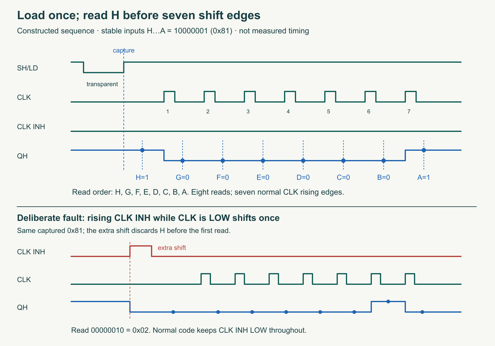
CLK INH deserves special attention. It is part of a gated clock structure: taking it high while CLK is low can create a shift edge. The normal program never takes it high. If a different design needs this gate, follow the datasheet’s clock-high condition for changing inhibit and recheck the full sequence. The optional fault argument intentionally violates that rule so the host model and later bench work can expose the resulting one-bit displacement.
Complete sampler and error behavior
Save the complete listing as sn74hc165-input-snapshot.py (sn74hc165-input-snapshot.py inside ZIP). On the selected Pico firmware, run it directly or copy it to main.py after reviewing the wiring. The default phase is 10 microseconds (µs). That is an intentionally slow software pacing choice, not a measured general-purpose input/output (GPIO) edge rate or a claimed 3.3 V worst-case timing characterization. The datasheet timing tables must be read at their stated conditions; this article does not invent a value between table voltages.
"""TI SN74HC165N at 3.3 V; original Pico / MicroPython 1.26.0.
The injected pin/delay interface is also exercised by the host model tests.
No physical timing or target execution is claimed.
"""


class SnapshotReader:
    def __init__(self, load, clock, inhibit, serial_out, delay_us):
        self.load, self.clock, self.inhibit = load, clock, inhibit
        self.serial_out, self.delay_us = serial_out, delay_us
        self.clock.value(0)
        self.inhibit.value(0)  # Normal operation never raises CLK INH.
        self.load.value(1)

    def capture(self, phase_us=10, extra_inhibit_edge=False):
        if not isinstance(phase_us, int) or phase_us < 10 or phase_us > 100000:
            raise ValueError('phase_us must be an integer from 10 to 100000')
        try:
            self.clock.value(0)
            self.inhibit.value(0)
            self.load.value(0)  # Transparent parallel load.
            self.delay_us(phase_us)
            self.load.value(1)  # Preserve this parallel pattern for shifting.
            self.delay_us(phase_us)
            if extra_inhibit_edge:
                # Deliberate teaching fault: a rising CLK INH with CLK low shifts.
                self.inhibit.value(1)
                self.delay_us(phase_us)
                self.inhibit.value(0)
                self.delay_us(phase_us)
            raw = 0
            for index in range(8):
                bit = self.serial_out.value()  # H exists BEFORE the first clock.
                if bit not in (0, 1):
                    raise ValueError('GPIO sample was not 0 or 1')
                raw = (raw << 1) | bit
                if index < 7:
                    self.clock.value(1)
                    self.delay_us(phase_us)
                    self.clock.value(0)
                    self.delay_us(phase_us)
            return {'raw': raw, 'pressed_mask': raw ^ 0xff,
                    'labels_A_to_H': tuple((raw >> bit) & 1 for bit in range(8)),
                    'deliberate_inhibit_fault': bool(extra_inhibit_edge)}
        finally:
            # Inhibit is lowered, never raised, while clock returns low.
            self.inhibit.value(0)
            self.clock.value(0)
            self.load.value(1)


def run(reader, sleep_ms, emit=print, cycles=None):
    iteration = 0
    while cycles is None or iteration < cycles:
        try:
            emit(reader.capture())
        except (OSError, ValueError) as exc:
            emit({'raw': None, 'pressed_mask': None, 'error': str(exc)})
        iteration += 1
        sleep_ms(200)


def main():
    from machine import Pin
    from time import sleep_us, sleep_ms
    reader = SnapshotReader(Pin(2, Pin.OUT, value=1),
                            Pin(3, Pin.OUT, value=0),
                            Pin(5, Pin.OUT, value=0),
                            Pin(4, Pin.IN), sleep_us)
    print('Raw bit7..bit0 = H..A; pressed mask uses 1 for a closed button.')
    run(reader, sleep_ms)


if __name__ == '__main__':
    main()
The finally block restores the control defaults even if an injected read error interrupts a capture. The loop prints absent current data when a software read raises an error; it does not recycle the last byte as a fresh result. Physical disconnection is a different issue: a floating QH or a broken ground can still return an ordinary zero or one. This interface has no checksum, identity response or automatic wire-integrity detection. Inspect wiring and use deliberately known input patterns before trusting a panel.
For a slow observation, instantiate the same reader in the read–evaluate–print loop (REPL) and call capture(100000). The loading window itself lasts about 0.1 s of requested delay; wait until it has ended before changing a contact. Reading the held pattern then takes much longer. Interpreter overhead adds time, so use a logic analyser for actual boundary measurements. Leave extra_inhibit_edge false for normal use.
A bench sequence with falsifiable outcomes
- Start with every button released. The expected logical pattern is raw 0xFF and pressed_mask 0x00.
- Close A only, then H only. Expected raw bytes are 0xFE and 0x7F; their pressed masks are 0x01 and 0x80. If these exchange places, inspect bit interpretation before rewiring the circuit.
- Close A and H together. Expect raw 0x7E and pressed_mask 0x81. Confirm each remaining contact separately; a stuck input can otherwise hide behind one convenient pattern.
- Use the slow capture and change a different contact after parallel loading has ended. The current stored byte should remain the earlier pattern; the next capture should reflect the new contacts.
- For the deliberate gate fault, release A and H and close B–G, giving raw 0x81. Compare capture() with capture(extra_inhibit_edge=True). With grounded SER, the logical fault result is 0x02. Return to the normal call afterwards.
- Repeat contact transitions near the capture boundary. Record disagreement and bounce rather than calling each intermediate byte a valid user action.
Use the blank observation sheet (sn74hc165-input-snapshot-observations-blank.csv inside ZIP) for physical results. It contains no invented trials. The author host checks exercised the actual sampler against all 256 parallel bytes, known labels, post-capture input changes, both ordering traps, API failures and control cleanup. The model represents logic and sequencing; it does not reproduce analog thresholds, metastability, contact physics or propagation delay. No microcontroller unit (MCU) build, MCU execution or physical result is claimed.
Extend the lesson without hiding its limits
A later application can debounce successive snapshots by requiring a stable pattern for a chosen interval. Choose that interval from actual switch observations and keep raw data available during diagnosis. Fast encoders, narrow pulses and safety interlocks need different acquisition requirements; a slow polled switch panel is the intended experiment here. For introductory circuit practice, revisit the site’s electronics lessons and the loaded voltage-divider experiment to see why input loading must be considered rather than assumed away.
Challenge: Can two captures of 0xFF prove that nobody pressed a switch between them? Answer: No. Each capture describes its own sampling boundary. A brief press and release between those boundaries leaves no stored event. Faster polling changes the missed-event window, but the parallel register alone is not an event recorder.
Primary sources and revision checks
- TI SNx4HC165 datasheet, SCLS116H, revision H: exact PDIP pin functions, clock/load behavior, operating conditions and limits.
- TI SN74HC165N orderable part page: selected N PDIP variant. The source review on 20 October 2026 did not identify a separate catalog-device errata document; that is not proof that none exists.
- Raspberry Pi Pico documentation and official original Pico pinout: board power and physical header mapping.
- MicroPython 1.26.0 Pin API: selected software baseline and digital input/output interface.
Download the complete experiment sources (ZIP): full programs, full-size PNG and editable SVG diagrams, and blank worksheets in separate experiment folders. The complete program remains inline above.