A memory-card audio player gives a small Christmas tree a different voice from a piezo melody generator. Here a Raspberry Pi Pico requests an original synthesized Jingle Bells audio file from a DFRobot DFPlayer Mini. The module drives a loudspeaker, while a transistor switches six separate red light-emitting diodes (LEDs). The lights run a simple independent animation: they are not synchronized to the audio decoder.
Verification: this is an unbuilt engineering prototype. The actual command encoder and animation logic pass host software tests. No Pico execution, module playback, supply-current measurement, acoustic test, thermal test or enclosure fit is claimed. Build and check the open circuit before designing an enclosure.
The exact reference design
Use the original non-wireless Raspberry Pi Pico based on RP2040, the genuine DFRobot DFR0299 module and an 8 Ω loudspeaker rated for at least 3 W. That speaker rating is its capacity, not a promise that the module delivers 3 W. MicroPython 1.26.0 for RPI_PICO is the selected reproducible software reference; it has not been executed on a board here. Do not substitute Pico W, another audio module or a similarly named transistor without reviewing its connections.
The control connections are general-purpose input/output (GPIO) pins. The Pico sends commands through a universal asynchronous receiver/transmitter (UART), a serial link with separate transmit and receive signals. This design uses only its transmit wire. The module’s TX and BUSY outputs are deliberately left unconnected. There is no acknowledgement, card detection or successful-playback report. A completed software write proves only that the local UART accepted the command bytes.
Power before sound
Use one regulated low-voltage direct-current (DC) source set to 4.5 V, with at least 1 A capacity and current limiting. Keep the voltage directly at the DFPlayer within 4.275–4.725 V, including startup, ripple and load transients. The source’s current rating and the suggested capacitors do not prove this. Begin at low volume and verify voltage and stability with appropriate instruments.
This deliberate supply window stays inside DFRobot’s 3.2–5 V operating specification. It also feeds the Pico’s VSYS input, physical pin 39. The Pico’s own regulator provides the 3.3 V LED rail. Do not feed the speaker module from Pico’s 3.3 V output, and do not feed external voltage into 3V3(OUT).
No Universal Serial Bus (USB) cable is connected during assembled operation. To program the Pico over USB, disconnect it from the entire external harness, including UART, power and LED wires. This prevents an independently powered controller output from feeding an unpowered audio module. After programming, remove USB, disconnect the external source, assemble the wiring and then apply the single external supply. No battery charger or mains circuit is part of this project.
Circuit schematics
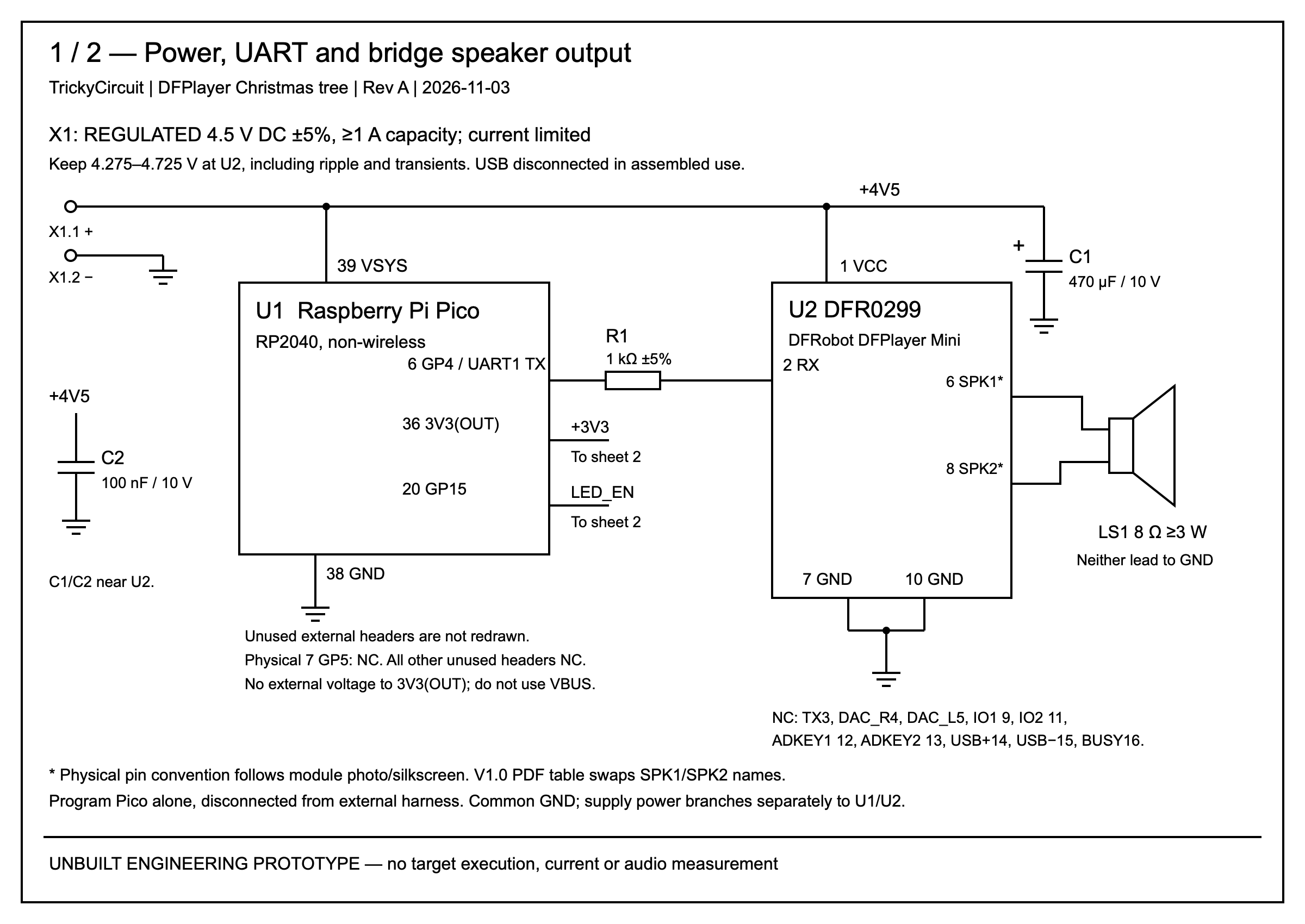
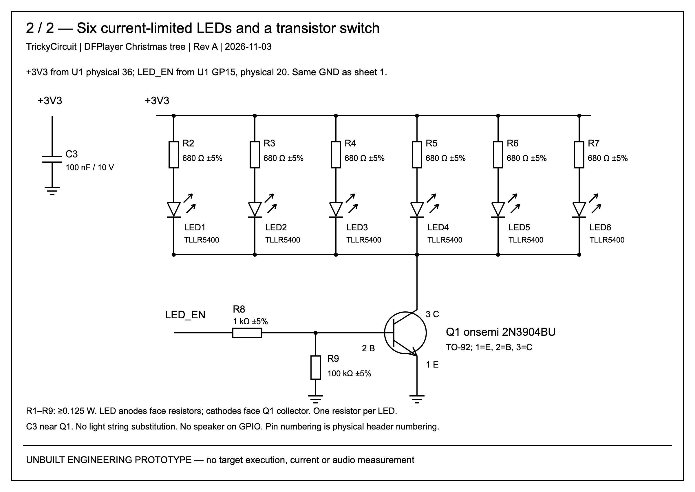
The symbols represent the external circuit, not the internal circuitry of either development module. Dots mark connected branches. Named nets join the sheets. Unused module terminals are explicitly listed as not connected (NC). These drawings are not printed circuit board layouts.
Bill of materials
| Reference | Quantity | Part/value |
|---|---|---|
| U1 | 1 | Original Raspberry Pi Pico, RP2040, non-wireless |
| U2 | 1 | DFRobot DFR0299 DFPlayer Mini |
| LS1 | 1 | 8 Ω speaker, rated at least 3 W |
| LED1–LED6 | 6 | Vishay TLLR5400 low-current red LED |
| Q1 | 1 | onsemi 2N3904BU TO-92; 1 emitter, 2 base, 3 collector |
| R1, R8 | 1 each | 1 kΩ ±5%, at least 0.125 W |
| R2–R7 | 6 | 680 Ω ±5%, at least 0.125 W |
| R9 | 1 | 100 kΩ ±5%, at least 0.125 W |
| C1 | 1 | 470 µF electrolytic, ±20%, at least 10 V; observe polarity |
| C2, C3 | 1 each | 100 nF nonpolar ceramic, ±20%, at least 10 V |
| X1/source | 1 | Insulated two-terminal input for regulated 4.5 V source described above |
| Storage | 1 | microSD (Secure Digital) card up to 32 GB; FAT16/FAT32 File Allocation Table format; use a dedicated card |
Use insulated wire, a suitable assembly board and strain relief. Place C1 and C2 close to U2; connect C1’s positive lead to +4V5. Place C3 near the LED driver. Route the source and ground branches separately to the controller and audio module before joining at the common supply connection. Do not run the speaker current through a thin controller-ground jumper.
Exact connections and a datasheet discrepancy
Connect Pico physical pin 6, GP4/UART1 TX, through R1 to DFPlayer RX pin 2. The Pico uses 3.3 V logic. The series resistor follows the manufacturer’s connection recommendation, but is not a universal level converter. GP5, physical pin 7, is assigned as the UART receive pin in code but remains physically unconnected. Do not add a return wire without separately qualifying its voltage.
Connect the speaker only between the two amplifier terminals, physical module positions 6 and 8. This is a bridge-tied load (BTL): both terminals are driven. Neither is ground. Never attach a grounded oscilloscope clip to either output; use an appropriate differential measurement method. The separate DAC_L/DAC_R line outputs, named for the digital-to-analogue converter, are unused and must not be confused with the speaker outputs.
The official DFRobot V1.0 PDF contains an internal inconsistency: its module photograph and table swap the names SPK1 and SPK2. The schematic follows the photograph/silkscreen convention, physical 6=SPK1 and 8=SPK2. Confirm the exact board’s printed labels and orientation before assembly. The important connection is a speaker across those two amplified outputs, never from one of them to ground.
Pico physical pin 20, GP15, drives R8 and Q1’s base. Q1 is an NPN bipolar junction transistor, named for its n-type, p-type and n-type semiconductor regions. Its emitter returns to ground and its collector joins all six LED cathodes. Each anode has its own resistor to 3.3 V. R9 pulls the base toward ground while it is not actively driven. Do not replace these branches with a high-power LED strip.
What the numbers do and do not establish
For an illustrative 3.3 V rail, LED drop 1.9 V and transistor drop 0.1 V, each branch carries (3.3−1.9−0.1)/680 ≈ 1.91 mA; six total approximately 11.47 mA. These voltage drops are examples, not measured brightness or guaranteed transistor saturation. The base-current example is (3.3−0.8)/1000 = 2.5 mA.
A resistor-only bound at 3.6 V, 646 Ω minimum resistance and a shorted LED gives 5.57 mA per branch, 33.44 mA across six, and 20.1 mW in each resistor. It does not cover a short that bypasses a resistor. The selected LED’s limit must still be checked against the actual component and operating conditions.
An ideal rail-limited sine wave across an 8 Ω bridge load at the upper 4.725 V supply would give approximately 4.725²/(2×8)=1.40 W. Real output depends on amplifier losses, clipping, load impedance, file level and supply behavior. This is an idealized calculation, not an output specification or measurement. Likewise, 470 µF with a hypothetical 0.2 A, 1 ms current pulse changes by ΔV=IΔt/C≈0.43 V before other effects: a capacitor is not a replacement for a stable source.
Our own audio, not a borrowed recording
The included 0001.mp3 is converted from this project’s computer-generated, single-voice Jingle Bells preview. It contains a 32-second refrain and four-second pause in its original waveform. The conversion uses 22.05 kHz mono audio at 128 kbps. MP3 encoding can add delay or padding, so the encoded duration is not treated as exact physical playback timing.
The historical composition and score are distinct from rights in modern performances or arrangements. No commercial recording, vocal track or modern backing arrangement was downloaded. The synthetic waveform is a teaching asset, not a recording of this speaker. Check applicable rights before replacing it with another file; a song being old does not grant rights to any particular recording.
With the device off, put the file on a dedicated formatted card at /mp3/0001.mp3. Insert the card before powering up. The command uses the module’s MP3-folder selection rather than generic file index order. Do not hot-swap the card. If a Mac creates hidden ._ companions, inspect this card’s contents; do not run broad cleanup or erase unrelated files.
Complete source files
Copy main.py, df_tx.py and show.py to the Pico while it is disconnected from the external circuit. Start with the specified official MicroPython reference firmware. The code waits, requests a reset, selects card storage and sets volume to 10 on the module’s 0–30 scale. This is not a decibel setting or a guarantee of safe loudness. Begin with the speaker away from ears and increase only after checking the actual circuit.
Each cycle sends one play request, then runs a 32-second LED animation with 100 ms pulses every 500 ms. Another request is sent after 42 seconds. The fixed warm-up delays are not readiness tests. Missing cards, unsupported commands, audio-start latency or a disconnected speaker can all leave the lights blinking without sound. On a local write exception the program tries to turn the LEDs off and send stop; this is best-effort software behavior. Removing the supply is the reliable user-controlled way to stop an unresponsive module.
main.py
"""Reference: original Raspberry Pi Pico + MicroPython 1.26.0. Not board-tested.
Disconnect the external circuit while flashing; no USB in assembled operation.
Exact power, driver, silkscreen and pin details are in the article schematic.
"""
from machine import Pin, UART
from time import ticks_ms, ticks_diff, sleep_ms
from df_tx import Transmitter
from show import run

led = Pin(15, Pin.OUT, value=0)
# RX is explicitly assigned GP5 but LEFT UNCONNECTED in the schematic.
# Never connect DFRobot TX/BUSY without separately qualified interface levels.
uart = UART(1, baudrate=9600, bits=8, parity=None, stop=1,
            tx=Pin(4), rx=Pin(5))
run(Transmitter(uart, sleep_ms), led, ticks_ms, ticks_diff, sleep_ms)
df_tx.py
"""Original minimal TX-only protocol encoder for DFRobot DFR0299.

Protocol facts checked against DFRobot's public driver. No vendor code copied.
No acknowledgement, card detection, playback confirmation or synchronization.
Hardware wiring and target runtime remain separate publication gates.
"""

def frame(command, argument=0):
    if type(command) is not int or not 0 <= command <= 255:
        raise ValueError('command must be an unsigned byte')
    if type(argument) is not int or not 0 <= argument <= 65535:
        raise ValueError('argument must be an unsigned 16-bit integer')
    packet = bytearray((0x7e, 0xff, 6, command, 0, argument >> 8,
                        argument & 255, 0, 0, 0xef))
    checksum = (-sum(packet[1:7])) & 65535
    packet[7], packet[8] = checksum >> 8, checksum & 255
    return bytes(packet)


class Transmitter:
    """Inject UART.write and sleep_ms; a successful write is not playback."""
    def __init__(self, uart, sleep_ms):
        self.uart, self.sleep_ms = uart, sleep_ms

    def send(self, command, argument=0):
        data = frame(command, argument)
        sent = self.uart.write(data)
        if sent != len(data):
            raise OSError('UART did not accept the complete command')
        self.sleep_ms(20)  # Conservative command spacing, not a readiness test.

    def volume(self, value):
        if type(value) is not int or not 0 <= value <= 30:
            raise ValueError('volume must be 0..30')
        self.send(0x06, value)

    def play_mp3(self, number=1):
        if type(number) is not int or not 1 <= number <= 9999:
            raise ValueError('MP3-folder file number must be 1..9999')
        self.send(0x12, number)

    def stop(self):
        self.send(0x16)
show.py
"""Original timed light animation and TX-only audio requests. Not beat sync."""
class Show:
    def __init__(self, transmitter, led, ticks_ms, ticks_diff):
        self.transmitter, self.led = transmitter, led
        self.ticks_ms, self.ticks_diff = ticks_ms, ticks_diff
        self.started = None

    def step(self):
        now = self.ticks_ms()
        if self.started is None or self.ticks_diff(now, self.started) >= 42000:
            # A successful UART write does not prove file playback.
            self.led.value(0)
            self.transmitter.play_mp3(1)
            self.started = self.ticks_ms()
            now = self.started
        elapsed = self.ticks_diff(now, self.started)
        self.led.value(int(0 <= elapsed < 32000 and elapsed % 500 < 100))


def run(transmitter, led, ticks_ms, ticks_diff, sleep_ms):
    try:
        led.value(0)
        sleep_ms(3000)  # Fixed warm-up only; no card/readiness detection.
        transmitter.send(0x0c)  # Module reset.
        sleep_ms(3000)
        transmitter.send(0x09, 2)  # Select microSD storage.
        sleep_ms(250)
        transmitter.volume(10)  # Start quietly; not a dB or power guarantee.
        sleep_ms(100)
        show = Show(transmitter, led, ticks_ms, ticks_diff)
        while True:
            show.step()
            sleep_ms(5)
    finally:
        led.value(0)
        try:
            transmitter.stop()
        except OSError:
            pass  # Best-effort command only. Remove supply to silence hardware.
The delivered host suite contains 12 passing tests. It executes the actual command encoder, animation, initialization/cleanup paths and the entry point with hardware shims. Tests cover fixed wire vectors, partial UART writes, invalid input, note-independent light timing, timer rollover and avoiding a catch-up burst. These tests do not qualify the MicroPython runtime, analogue signals or module hardware.
Bench procedure and troubleshooting
- Disconnect all power. Verify resistor values, transistor lead order, LED and capacitor polarity, module orientation and common ground. Check that neither speaker terminal connects to ground.
- Program and check the bare Pico alone. Disconnect USB before attaching the external harness.
- Prepare the dedicated card and install it while the module is unpowered. Connect one LED branch first; inspect it before adding the other five.
- Verify the external source setting and current limit, then power the circuit at low volume. Check voltage at U2 and the Pico rail. If voltage collapses, the current limit activates, parts heat or resets occur, disconnect and diagnose; do not bypass protection.
- Confirm the actual file plays, finishes and repeats without unintended interruption. Check the light pattern independently. Lack of acknowledgement means the program itself cannot perform these observations.
- Measure each LED-resistor voltage and calculate current. A meter can average pulses; use a suitable instrument or deliberate test mode to examine peaks.
No sound: check card path, card format, volume, supply voltage and the speaker’s two-terminal connection. Buzz or resets: examine power routing and voltage under load before changing code. Wrong track: confirm the MP3 folder and exact filename. Lights without sound are not evidence of successful playback. Keep an unverified assembly supervised and away from small children.
Continue with the Pico ultrasonic theremin to explore generating a changing pitch directly. That is a separate circuit with a different pin assignment.
Challenge
Why can a light pulse begin before the first audible note even though both are requested in the same function? The local clock starts after the command is transmitted, while the audio module still has to interpret the request and read/decode the file. A shared command time is not a shared playback clock.
Primary references and files
- DFRobot DFR0299 documentation and its linked V1.0 datasheet.
- Manufacturer protocol implementation and file-selection example. The delivered driver is an independent minimal implementation, not copied vendor source.
- Raspberry Pi board and pin documentation; official MicroPython RPI_PICO releases.
- Vishay TLLR5400; onsemi 2N3904.
- Library of Congress historical Jingle Bells score.
- Original synthesized audio MP3; code, tests, calculations and editable schematic sources.