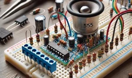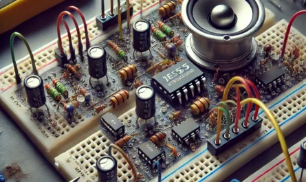
Make a small Christmas tree play a simple Jingle Bells refrain while red, green and yellow lights follow four different patterns. LUMA Music Rev C uses a passive piezo sounder and the official Espressif ESP32-C3-DevKitM-1. Its six light-emitting diodes (LEDs) form three independently switched pairs: the two LEDs in each pair always work together.
Design status: this is an unbuilt USB-powered engineering prototype. The animation and melody pass host software tests, and the supplied schematic has a clean KiCad ERC report. ESP32-C3 target compilation, flashing, real sound, current, temperature, startup transients and enclosure fit have not been verified. Simulation is not physical testing.
A general-purpose input/output (GPIO) is a controllable signal pin. Ground (GND) is the shared electrical reference. Universal Serial Bus (USB) supplies the board through its onboard Micro-USB connector; its regulator supplies the external 3.3 V rail. Pulse-width modulation (PWM) switches a pin repeatedly to excite the piezo. The LED Control (LEDC) peripheral creates that waveform. Each NPN transistor, named for its semiconductor regions, switches one LED pair without putting LED current through a GPIO.
Watch the calculated sequence
The English-labelled video uses the firmware’s exported timeline and synthetic audio. It is an illustrative computer simulation, not an assembled-device recording or a dimensional enclosure model.
Light sequence
The simplified Jingle Bells refrain has 16 bars, 49 notes and a tempo of 120 quarter notes per minute. It plays for 32 seconds, followed by a four-second silent, dark pause, then repeats.
| Time | Pattern |
|---|---|
| 0-8 s | Colour chase: red, green, yellow. A step every 500 ms; each step stays on for 300 ms. |
| 8-16 s | Alternating pairs: red+green, green+yellow, yellow+red. A step every 1 s; on for 650 ms. |
| 16-24 s | Overlapping wave each second: red at 0-350 ms, green at 250-600 ms, yellow at 500-850 ms. |
| 24-32 s | Accents: R, G+Y, G, R+Y, Y, R+G, R, Y. A step every 500 ms; on for 250 ms. |
| 32-36 s | All groups and sound off. |
Lights and melody share the same software clock. At most two groups are commanded on in a logical frame. The shortest tested interval between successive rising edges of one group is 500 ms. This is not a medical safety claim; do not point flashing lights into someone's eyes. Brightness has not been equalised by physical measurement.
preview/LUMA_RevC_EN_simulation.mp4 is generated from checks/timeline.csv, exported directly by the C++ player. Its sound is synthetic and its tree outline is illustrative. It is not a recording or a dimensional model of an assembled device. The melody is a simple single-voice arrangement, not a modern commercial recording.
Board and wiring
RGB means red, green and blue combined in a colour-mixing device; these are separate fixed-colour LEDs instead. JTAG (Joint Test Action Group) is the external debug interface. NC means not connected. A TO-92 is the specified transistor package, not a universal pin order.
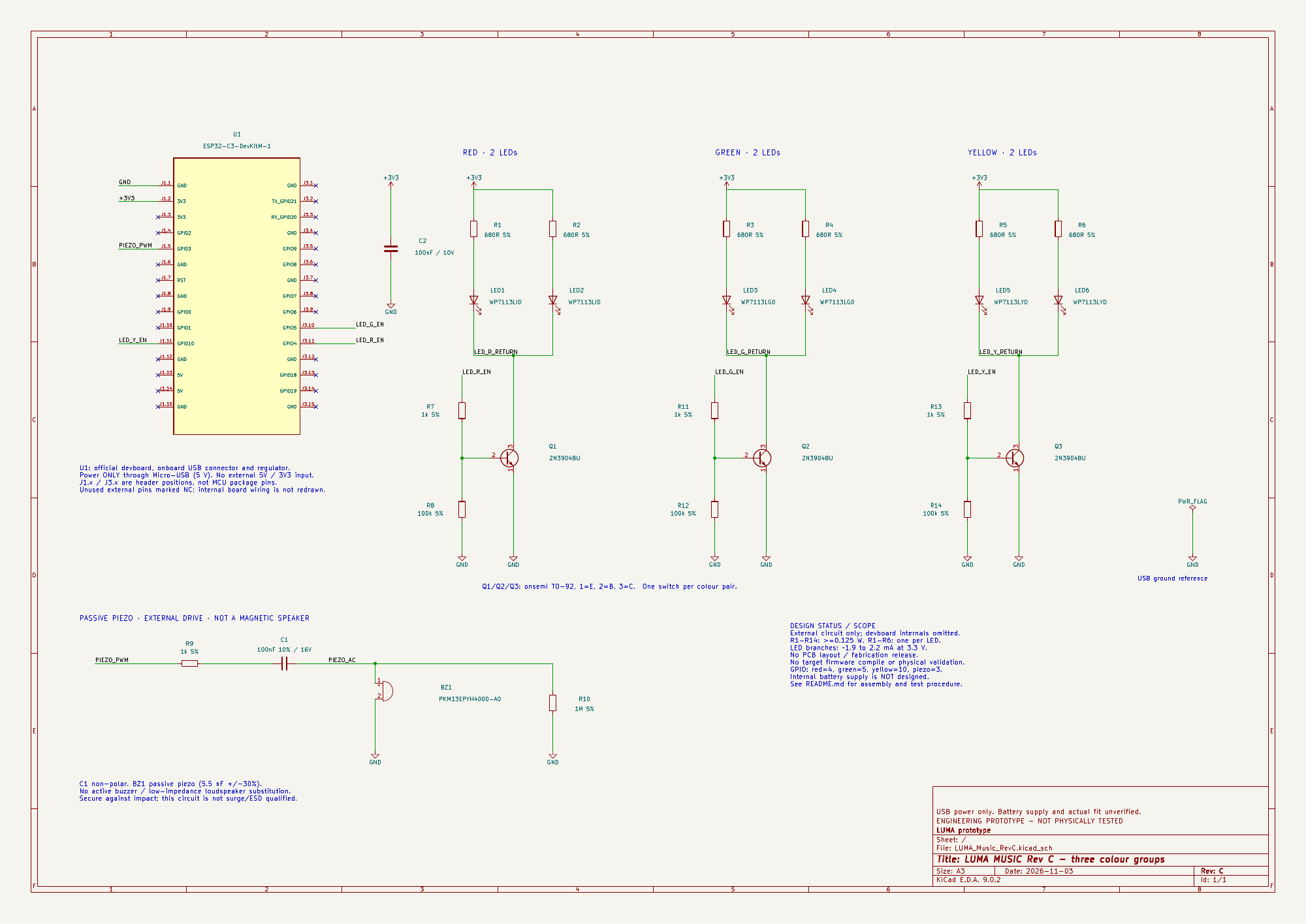
Reference board: the official Espressif ESP32-C3-DevKitM-1, not an arbitrary SuperMini. Use its onboard Micro-USB connector for power. GPIO numbers are not connector position numbers.
| Group | LEDs / part | GPIO | Header position | Switch | Base resistor / pulldown |
|---|---|---|---|---|---|
| Red | LED1-2 / WP7113LID | 4 | J3.11 | Q1 | R7 1 kOhm / R8 100 kOhm |
| Green | LED3-4 / WP7113LGD | 5 | J3.10 | Q2 | R11 1 kOhm / R12 100 kOhm |
| Yellow | LED5-6 / WP7113LYD | 10 | J1.11 | Q3 | R13 1 kOhm / R14 100 kOhm |
| Piezo | BZ1 | 3 | J1.5 | – | R9 1 kOhm and C1 100 nF in series |
GPIO6 was avoided because its reset pull-up could turn on a transistor before the program starts. GPIO4/5 cannot simultaneously be used for external JTAG. GPIO2/8/9 boot strapping pins are not used for these external circuits. The internal flash is not connected to the chosen external circuits. Real power-on and reset flashes still need testing.
For each pair: 3V3 goes through a separate 680 Ohm resistor to each LED anode. The pair's two cathodes join only the collector of its transistor. The emitter goes to GND. Its GPIO goes through its own 1 kOhm resistor to the base; its own 100 kOhm resistor connects base to GND. Do not connect cathodes of different colour groups together. Only the 3V3 and GND rails are common.
Q1-Q3 are onsemi 2N3904BU in TO-92. Manufacturer pin numbers: 1=emitter, 2=base, 3=collector. Check the actual package drawing rather than guessing from the silhouette. Do not substitute BC547 without checking and changing the pin connections.
Parts list
Nothing has been purchased. Availability has not been checked.
- 1 official ESP32-C3-DevKitM-1.
- 2 Kingbright WP7113LID red, 2 WP7113LGD green and 2 WP7113LYD yellow LEDs. These are 5 mm low-current parts characterised at 2 mA.
- R1-R6: 6 x 680 Ohm, +/-5%, at least 0.125 W. One per LED.
- Q1-Q3: 3 x onsemi 2N3904BU.
- R7, R9, R11, R13: 4 x 1 kOhm, +/-5%, at least 0.125 W.
- R8, R12, R14: 3 x 100 kOhm, +/-5%, at least 0.125 W.
- R10: 1 x 1 MOhm, +/-5%, at least 0.125 W.
- BZ1: 1 x Murata PKM13EPYH4000-A0, passive externally driven piezo, 12.6 mm diameter, 5.5 nF +/-30%, 4 kHz resonance.
- C1: 100 nF +/-10%, non-polar, at least 16 V; preferably film.
- C2: 100 nF ceramic, at least 10 V, between 3V3 and GND near the switches.
- USB data cable, protected 5 V supply rated for at least 1 A, insulated wire, heat-shrink tubing, prototyping board and insulating mounts.
Murata lists this family for discontinuation on 30 September 2027. It is a prototype choice, not a long-term production supply recommendation. Other LED colours or part numbers, ready-made strings and strips require a new calculation. In particular, do not automatically substitute higher-forward-voltage white or blue LEDs.
Piezo and power
Direct current (DC) can hold a steady bias across a component; the series capacitor blocks that steady component. Electrostatic discharge (ESD) is a sudden discharge of stored electrical charge. This prototype has not been qualified against it.
GPIO3 -> R9 1 kOhm -> C1 100 nF -> PIEZO_AC. BZ1 and R10 1 MOhm are parallel from PIEZO_AC to GND. Non-polar C1 blocks sustained DC bias; R10 discharges the node. Firmware requests zero PWM duty during rests and checks that API result.
Never connect a low-impedance magnetic speaker directly to a GPIO. An active buzzer with an internal oscillator will not reproduce this melody. Do not bend or strike the piezo: mechanical stress can generate voltage spikes. This circuit is not qualified for impact transients or ESD. Notes at 1047-1568 Hz are below the part's 4 kHz resonance, so real loudness is unknown. Do not increase voltage to make it louder without redesign.
Do not power the board through USB and the 5V/3V3 pins simultaneously. Never apply 5 V to a GPIO. A 5 V, 1 A source has load capacity in reserve; the device does not necessarily draw 1 A.
An internal battery supply is not designed. Do not connect AA/AAA cells, a 9 V battery, lithium cell or charging module directly to this circuit. Battery choice, holder, protected converter, switch, dimensions and layout need separate design. A finished USB power bank may be tried on the bench if it supports low loads without switching off, but compatibility and runtime are unverified. There is no charger inside the printed enclosure.
Calculated currents
VCE is the voltage from a transistor collector to its emitter. A typical forward voltage is an example from a part characteristic, not a guaranteed value for each LED.
Example assumptions: 3.3 V rail and 0.1 V transistor VCE. Typical LED forward voltages at 2 mA are 1.7 V red, 1.9 V green and 1.85 V yellow. With 680 Ohm, the approximate currents are 2.21 / 1.91 / 1.99 mA per LED; all six together would draw about 12.21 mA. These use typical values and do not guarantee actual current or equal brightness. Absolute maximum DC currents at 25 degrees C are 30 / 25 / 30 mA; these are limits, not design targets.
Each base draws approximately 2.6 mA, or about 7.8 mA for three simultaneously. LEDs draw from the board's 3V3 rail, not GPIO outputs. Each switch normally handles roughly 4 mA for its pair.
With a 3.6 V calculation boundary, a 646 Ohm resistor (-5%) and a shorted LED, the resistor-limited upper bound is 5.57 mA per branch, 11.15 mA per pair or 33.44 mA for six. Resistor power is at most 20.1 mW versus a 125 mW rating. This does not cover a short that bypasses the resistor. The 3.6 V figure is a calculation boundary, not an instruction to adjust the supply.
For each 1 kOhm GPIO resistor at -5%, the resistive bound is 3.79 mA. Three bases and a piezo edge together give 15.16 mA as an estimated load bound, not a separately published aggregate ESP32 current limit. Mechanical piezo spikes are excluded. Piezo maximum capacitance is 7.15 nF; calculations include C1 and R10 tolerances.
Firmware and first power-up
Firmware is the program running on the controller. The Arduino integrated development environment (IDE) builds and uploads it. An application programming interface (API) defines the functions it calls. USB CDC (Communications Device Class) is a USB serial-interface option; the reference board uses its separate USB-to-serial bridge. Flash is nonvolatile program memory on the board.
- In Arduino IDE, use the official esp32 by Espressif Systems, 3.3.2 reference package (3.x API). The 2.x LEDC API is different and unsupported here.
- Open
firmware/LumaMusic/LumaMusic.ino, keepingplayer.hbeside it. - Select ESP32C3 Dev Module, 4MB flash and USB CDC On Boot: Disabled for the official USB-UART board. Select the port. First Verify and Upload with no external circuit attached.
- Disconnect power. Assemble one LED and one switch; check markings, values, polarity and absence of shorts. Add the remaining groups and piezo only after this check.
- Apply USB power under supervision. Check each group, patterns, pause, reset, 3V3 voltage and absence of heating. Disconnect immediately for unusual heat, smell, voltage drop, repeated resets or other abnormal behaviour. Do not defeat supply protection.
- Estimate LED current by measuring voltage across its resistor: I=V/R. A multimeter may average a blinking signal; peak measurements need suitable equipment. Actual loudness and transient behaviour are not established by calculation.
At startup, the program configures each LED GPIO as an output, then writes LOW. Tone frequency and duty are checked with separate API calls. After a detected LEDC error it requests all LEDs off, stops further playback and attempts to stop PWM and drive the piezo pin LOW. If PWM mute, peripheral detach and the GPIO fallback all fail, physical silence is not guaranteed. A host test explicitly demonstrates this limit. Disconnect USB if behaviour is abnormal. Wi-Fi/Bluetooth are not started.
The code was compiled on the host with hardware calls replaced by test models. A real ESP32-C3 target build and bench testing remain mandatory. Arduino-ESP32 3.3.2 source was reviewed for GPIO ownership and LEDC return semantics; this is not a target compilation claim.
Enclosure: leave the first build open
The LUMA concept has 26 nominal LED holes, but this circuit uses only six LEDs. An illustrative tree outline does not establish a printable enclosure or component fit. The supplied mechanical notes are not a fit check of the real DevKitM-1, three switches, wiring, USB plug or piezo. No revised STL is provided by this article. Trial-print holes for the actual LED lens and flange, design insulated mounts and a strain-relieved USB entry, and verify clearances before closing a case. Keep the first powered experiment open and supervised. Batteries and an internal charger are outside this design.
Complete firmware
Select the official Arduino-ESP32 3.3.2 reference package and ESP32C3 Dev Module for the reference board. The source requires the 3.x API. Version 3.3.2 API source was reviewed, but an ESP32-C3 target build has not been performed here. The installed local tools permit host C++ tests only. Keep both files in the same LumaMusic sketch directory.
LumaMusic.ino
/* LUMA music/LED prototype, Arduino-ESP32 3.x, ESP32-C3 only.
   GPIO3: 1k + DC-block capacitor + passive piezo (see wiring diagram).
   GPIO4/5/10: separate 1k + 2N3904 switches for red/green/yellow pairs.
   No Wi-Fi or Bluetooth is started. No network or external libraries.
   The sketch repeats a 32-second refrain, then rests for 4 seconds.
*/
#include <Arduino.h>
#include <esp_arduino_version.h>
#include "player.h"
#if ESP_ARDUINO_VERSION_MAJOR < 3
#error "Install Arduino-ESP32 3.x. The LEDC API in 2.x is different."
#endif
#if !defined(CONFIG_IDF_TARGET_ESP32C3)
#error "This wiring is for an ESP32-C3 devboard. Select ESP32C3 Dev Module."
#endif

constexpr uint8_t kPiezoPin = 3;
constexpr uint8_t kLedPins[] = {4, 5, 10}; // red, green, yellow
luma::Player player;
bool outputReady = false;
uint16_t previousTone = 0;

void failSilent() {
  // Best effort only: arbitrary peripheral/GPIO failure cannot guarantee
  // physical silence. Disconnect USB if the device behaves abnormally.
  for (uint8_t pin : kLedPins) digitalWrite(pin, LOW);
  if (outputReady) {
    ledcWrite(kPiezoPin, 0);
    ledcDetach(kPiezoPin);
  }
  outputReady = false;
  pinMode(kPiezoPin, OUTPUT);
  digitalWrite(kPiezoPin, LOW);
}

void setup() {
  for (uint8_t pin : kLedPins) {
    pinMode(pin, OUTPUT);
    digitalWrite(pin, LOW); // Arduino-ESP32 requires GPIO ownership first.
  }
  pinMode(kPiezoPin, OUTPUT);
  digitalWrite(kPiezoPin, LOW);
  outputReady = ledcAttach(kPiezoPin, 1000, 10);
  if (!outputReady) {
    failSilent();
    return;
  }
  // Unlike ledcWriteTone(pin, 0), ledcWrite reports stop failures.
  if (!ledcWrite(kPiezoPin, 0)) {
    failSilent();
    return;
  }
  player.reset(millis());
}

void loop() {
  if (outputReady) {
    const luma::Frame next = player.frame(millis());
    if (next.frequency != previousTone) {
      const bool success = next.frequency == 0
          ? ledcWrite(kPiezoPin, 0)
          : (ledcWriteTone(kPiezoPin, next.frequency) != 0 &&
             ledcWrite(kPiezoPin, 511)); // Recheck 10-bit tone duty explicitly.
      if (!success) {
        failSilent();
        delay(1);
        return;
      }
      previousTone = next.frequency;
    }
    for (uint8_t i = 0; i < 3; ++i) {
      digitalWrite(kLedPins[i], (next.ledMask & (1U << i)) ? HIGH : LOW);
    }
  }
  delay(1); // Yield; LEDs and melody are timed by millis(), not long delays.
}
player.h
#pragma once
#include <cstddef>
#include <cstdint>
namespace luma {
// Original single-voice simplified arrangement of the public-domain refrain.
// C6=1047, D6=1175, E6=1319, F6=1397, G6=1568 Hz (rounded).
// One tick is an eighth note, 250 ms at 120 quarter-notes/minute.
struct Note { uint16_t frequency; uint8_t ticks; };
constexpr Note kScore[] = {
{1319,2},{1319,2},{1319,4}, // 1
{1319,2},{1319,2},{1319,4}, // 2
{1319,2},{1568,2},{1047,3},{1175,1}, // 3
{1319,8}, // 4
{1397,2},{1397,2},{1397,3},{1397,1}, // 5
{1397,2},{1319,2},{1319,2},{1319,2}, // 6
{1319,2},{1175,2},{1175,2},{1319,2}, // 7
{1175,4},{1568,4}, // 8
{1319,2},{1319,2},{1319,4}, // 9
{1319,2},{1319,2},{1319,4}, // 10
{1319,2},{1568,2},{1047,3},{1175,1}, // 11
{1319,8}, // 12
{1397,2},{1397,2},{1397,3},{1397,1}, // 13
{1397,2},{1319,2},{1319,2},{1319,2}, // 14
{1568,2},{1568,2},{1397,2},{1175,2}, // 15
{1047,8} // 16
};
constexpr uint32_t kTickMs = 250;
constexpr uint32_t kBeatMs = 500;
constexpr uint32_t kPauseMs = 4000;
// Three independently switched groups: bit0 red, bit1 green, bit2 yellow.
// Four 8-second phrases, all derived from the same music clock.
inline uint8_t lightMask(uint32_t elapsed) {
if (elapsed >= 32000) return 0;
const uint32_t phrase = elapsed / 8000;
const uint32_t local = elapsed % 8000;
if (phrase == 0) { // single-colour chase, one quarter note per step
return local % 500 < 300 ? uint8_t(1U << ((local / 500) % 3)) : 0;
}
if (phrase == 1) { // alternating pairs, one half note per step
constexpr uint8_t pairs[] = {3, 6, 5};
return local % 1000 < 650 ? pairs[(local / 1000) % 3] : 0;
}
if (phrase == 2) { // overlapping wave, different start/stop times
const uint32_t phase = local % 1000;
uint8_t mask = 0;
if (phase < 350) mask |= 1;
if (phase >= 250 && phase < 600) mask |= 2;
if (phase >= 500 && phase < 850) mask |= 4;
return mask;
}
constexpr uint8_t accents[] = {1, 6, 2, 5, 4, 3, 1, 4};
return local % 500 < 250 ? accents[(local / 500) % 8] : 0;
}
constexpr size_t scoreEventCount() { return sizeof(kScore)/sizeof(kScore[0]); }
constexpr uint32_t scoreDurationMs() {
uint32_t ticks = 0;
for (const auto &n : kScore) ticks += n.ticks;
return ticks * kTickMs;
}
constexpr uint32_t kCycleMs = scoreDurationMs() + kPauseMs;
static_assert(scoreDurationMs() == 32000, "Score must contain sixteen 4/4 bars");
struct Frame { uint16_t frequency; uint8_t ledMask; };
class Player {
public:
void reset(uint32_t now) { start_ = now; }
Frame frame(uint32_t now) {
uint32_t elapsed = now - start_; // Unsigned subtraction handles millis wrap.
if (elapsed >= kCycleMs) {
const uint32_t cycles = elapsed / kCycleMs;
start_ += cycles * kCycleMs;
elapsed %= kCycleMs;
}
if (elapsed >= scoreDurationMs()) return {0, false};
const uint8_t mask = lightMask(elapsed);
uint32_t onset = 0;
for (const auto ¬e : kScore) {
const uint32_t duration = note.ticks * kTickMs;
if (elapsed < onset + duration) {
// Last 10% of every note is a rest, including repeated pitches.
const bool sounding = elapsed - onset < duration * 9 / 10;
return {sounding ? note.frequency : uint16_t{0}, mask};
}
onset += duration;
}
return {0, false};
}
private:
uint32_t start_ = 0;
};
} // namespace luma
What has actually been checked
The supplied KiCad 9.0.2 electrical rules check (ERC) reports zero errors and zero warnings, without exclusions. The independent connection contract checks 27 components, 20 active nets and 24 unused board-header pins. This computer reran the host player and seven adapter modes, plus the numerical checks; it did not rerun KiCad ERC because KiCad CLI is not installed. Host substitutes test hardware calls; they do not establish real GPIO timing, firmware compilation for ESP32-C3, acoustic output or physical fault recovery.
The logical timeline has 36,001 one-millisecond samples, 49 note attacks and different on-times for the three groups. Its maximum of two enabled groups describes one computed frame. GPIO writes happen sequentially, so transitions are not guaranteed simultaneous: a brief three-group overlap is possible. The circuit calculations also cover all six LEDs. The video is a visualization of that exported timeline with synthesized sound, not a hardware recording.
First experiment and troubleshooting
Use the power-off checks above first. If one colour never lights, check that pair's two separate resistors, LED polarity, transistor pin order, common ground and exact GPIO/header position. If all colours follow one another, check for accidentally joined cathodes from the earlier one-channel circuit. If the melody stays at one pitch, verify that BZ1 is a passive piezo rather than an active buzzer. If the program fails or the board repeatedly resets, disconnect USB and investigate wiring and supply; do not disable protection or increase voltage. A failed peripheral can defeat the best-effort software mute.
Challenge
What would happen if the green and red cathode returns were connected together? Their switches would no longer control separate groups: either transistor could sink current for both colours. The correct repair is separate return nets, not a new animation pattern.
Download and related experiment
The download includes the English guide, editable KiCad project and SVG, PDF schematic, full code, host tests, numerical reports and English simulation video. Component availability, target compilation and physical performance remain unverified. For another independent microcontroller sound experiment, see the Pico ultrasonic theremin. Its wiring and board are different.
Primary sources
- Espressif DevKitM-1 guide, power and header mapping
- ESP32-C3 datasheet and GPIO reset states
- Espressif Arduino LEDC API
- Arduino-ESP32 3.3.2 GPIO source
- Arduino-ESP32 3.3.2 LEDC source
- Kingbright WP7113LID red
- Kingbright WP7113LGD green
- Kingbright WP7113LYD yellow
- onsemi 2N3904
- Murata piezo catalogue
- Murata direct-drive circuits
- Murata mechanical stress
- Murata discontinuation notice
- Library of Congress: original 1857 song