Both temperature sensors in this lab answer to the seven-bit I²C address 0x18. With a TCA9548A between them and a Raspberry Pi Pico, the Pico can make the same register request on either branch. You will verify the route at the switch, read the device on that route, disconnect it, and then repeat on the other branch. A second run with one sensor removed shows which part of the connection failed and whether the other branch can still be read.
The address and the route are separate
The Pico addresses the TCA9548A itself at 0x70. A control write contains exactly one data byte with no register-pointer byte. Bit 0 connects channel 0 and bit 1 connects channel 1. A successful write ends with a STOP. The requested channel selection takes effect after that STOP. The program waits 1 ms after each stop-ending operation, outside the repeated START inside a sensor read. TI lists a minimum 4.7 µs bus-free interval between STOP and the next START in Standard-mode. A separate one-byte read at 0x70 confirms the control register before the Pico addresses the selected sensor.
The program clears the route and reads back 0x00 before selecting the next branch. Keep both sensor branches off whenever you change wiring, and keep the USB disconnected while you work. Both MCP9808 devices would acknowledge the same address if their routes were joined, and their open-drain outputs could pull different bits low in the same read. The program permits only 0x00, 0x01 and 0x02.
| Control byte | Connected branch | Intended sensor access |
|---|---|---|
0x00 |
None | Isolation check only |
0x01 |
Channel 0, label A | 0x18 on A |
0x02 |
Channel 1, label B | 0x18 on B |
Build one 3.3 V fixture
Use an original Raspberry Pi Pico with the RP2040, a TI TCA9548APWR in the 24-pin PW TSSOP, and two Microchip MCP9808-E/MS parts in the 8-pin MSOP. Use blank 0.65 mm pitch adapters with the correct land pattern for each package. Mark pin 1 on each populated adapter and check the adapter-to-header mapping by continuity before inserting it. Make each sensor adapter removable as a four-wire group and mark it A or B. Keep wires short, especially the common return and each SDA/SCL pair.
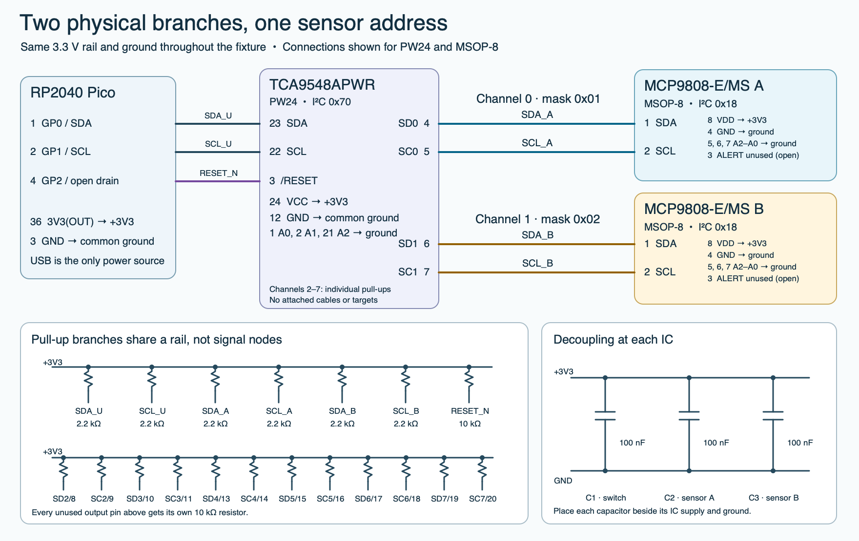
- Power the entire fixture from the Pico USB connection. Use Pico header pin 36,
3V3(OUT), for the positive rail and pin 3 for ground. Connect switch pin 24 (VCC) and both sensor pins 8 (VDD) to this rail. Connect switch pin 12 and both sensor pins 4 to ground. Put a 100 nF ceramic capacitor between the supply and ground beside each IC. The switch and both sensors operate at 3.3 V within their published ranges. Keep every fixture signal within that supply domain. - Ground switch A0, A1 and A2 at PW pins 1, 2 and 21, respectively. Connect Pico GP0 (header pin 1) to switch SDA (pin 23), GP1 (header pin 2) to SCL (pin 22), and GP2 (header pin 4) to active-low RESET (pin 3). Put 10 kΩ from RESET to 3.3 V. GP2 pulls RESET down or releases the line to the resistor.
- For A, connect switch pin 4 (SD0) to sensor pin 1 (SDA) and switch pin 5 (SC0) to sensor pin 2 (SCL). For B, use switch pins 6 (SD1) and 7 (SC1) to the same two pin numbers on its own sensor. Ground all three straps on each sensor, pins 5, 6 and 7. The power-on configuration disables ALERT, so leave pin 3 open for this read-only lab.
- Add six 2.2 kΩ, 1% resistors. Place one to 3.3 V on each SDA and SCL of the upstream segment and on each of the two used branches. Keep branch pull-ups on the carrier so they remain connected when an adapter is removed. Connect each unused switch channel pin 8–11 and 13–20 to 3.3 V through its own 10 kΩ resistor as shown. Leave those channels without targets or cables.
Before attaching USB, inspect for bridges and confirm that SDA and SCL from branch A have no direct continuity to the corresponding lines on B. Confirm the common ground on both adapters. Start from a fully unpowered fixture so the switch sees a proper power-up. If USB was just disconnected, allow the rail to fall close to ground before reconnecting. Attach measurement equipment ground only to circuit ground, with any logic-analyzer inputs set for 3.3 V. Keep external power outputs disconnected. Measure the rail after attaching USB. Use the calculations below only for a rail between 3.20 V and 3.40 V.
Check the pull-ups with a scope
The program uses 100 kHz Standard-mode. With one route connected, the upstream 2.2 kΩ and the selected branch’s 2.2 kΩ both contribute pull-up current on each signal. Treating the pass switch as a short gives 1.10 kΩ effective external pull-up and about 2.64 mA per line at a 0.4 V low on a nominal 3.3 V rail. At 3.40 V, allowing 1% resistor tolerance and the RP2040’s enabled pull-up at its 50 kΩ minimum gives about 2.82 mA at 0.4 V. The 0.4 V point is the datasheet test point for the MCP9808 SDA driver and the switch’s own SDA driver at 3 mA. Actual current varies with the actual low voltage.
First-pass rise-time estimate. t30–70 ≈ 0.8473 × Rpull-up × Cbus. An isolated 120 pF segment with 2.2 kΩ gives about 224 ns. Two such segments joined give the same lumped estimate with 240 pF and 1.10 kΩ. These capacitances are planning assumptions that include the measurement probe.
Measure the 30–70% rise and 70–30% fall at the upstream pair and at each selected branch. Use a high-impedance probe and short ground connection. The MCP9808 specifies 20–300 ns for both transitions. Use that window on the active sensor path even at the lower clock rate. Check the driven low on each line, including the sensor’s SDA ACK on both sides of the switch. A sensor low seen across the pass switch can be higher than at the sensor. Verify that the driven low meets 0.4 V at its source and the far-side voltage stays within the receiver’s input-low limit. If a measurement falls outside the limits, shorten wiring or reduce probe loading before reconsidering the pull-ups. The unused-channel pull-ups remain on their own isolated pins.
Read and decode one physical branch
After switch readback, the code reads the sensor manufacturer’s word at 0x06 (expected 0x0054) and the device/revision word at 0x07 (device byte 0x04, lower byte is the revision). These IDs identify the device type. The cable labels and the verified switch mask identify its physical branch. Each sensor register read writes an 8-bit pointer, issues a repeated START and reads the requested data. The ID and ambient words come high byte first. The one-byte resolution register at 0x08 is read separately. The separate switch control write still requires its own STOP before that sensor transaction.
Ambient register 0x05 has three alert flags above a signed 13-bit value. Mask with 0x1FFF, subtract 0x2000 when bit 12 is set, and divide by 16. For example, the calculated word 0x1FB0 decodes to −5.0000 °C. A decoded unit of 0.0625 °C is the finest encoded step. The actual configured step depends on the resolution register, which this program reports as resolution_code. Codes 0 through 3 correspond to 0.5, 0.25, 0.125 and 0.0625 °C. Code 3 has a typical conversion time of 250 ms. This example waits 750 ms at startup and leaves about a second between sweeps. Both sensors stay powered and convert while their bus routes are off.
Save the program as main.py on the Pico under MicroPython v1.25.0 for RP2. Open the USB serial console, then reset or reboot the Pico. The program emits one JSON line per sweep for up to 12 sweeps. JSON integers print in decimal, so a successful maker ID appears as 84 and the masks as 1 and 2. At normal exit or Ctrl-C, the cleanup holds the switch RESET low. Use another reboot or run to start again.
"""Two MCP9808 branches on a TCA9548A. Run on an RP2040 Pico."""

SWITCH_ADDR = 0x70
SENSOR_ADDR = 0x18
BRANCHES = (("A", 0x01), ("B", 0x02))
AMBIENT_REG = 0x05
MAKER_REG = 0x06
DEVICE_REG = 0x07
RESOLUTION_REG = 0x08


class RoutingError(Exception):
    pass


def temperature_c(raw):
    counts = raw & 0x1FFF
    if counts & 0x1000:
        counts -= 0x2000
    return counts / 16.0


class RoutedSensors:
    def __init__(self, bus, reset_pin, wait_ms):
        self.bus = bus
        self.reset_pin = reset_pin
        self.wait_ms = wait_ms
        self.mask = None

    def hold_reset(self):
        self.mask = None
        self.reset_pin.value(0)

    def _transfer(self, operation, *arguments):
        try:
            return operation(*arguments)
        finally:
            # Each operation ends with STOP on success. Leave the bus idle
            # before any following START. This is outside repeated STARTs.
            self.wait_ms(1)

    def _read_mask(self):
        data = self._transfer(self.bus.readfrom, SWITCH_ADDR, 1, True)
        if len(data) != 1:
            raise RoutingError("short switch read")
        return data[0]

    def _check_isolation(self):
        try:
            self._transfer(self.bus.readfrom, SENSOR_ADDR, 1, True)
        except OSError:
            if self._read_mask() != 0:
                raise RoutingError("switch changed during isolation check")
            return
        raise RoutingError("sensor address responded with all routes off")

    def _reset_to_off(self):
        self.hold_reset()
        self.wait_ms(1)
        self.reset_pin.value(1)
        self.wait_ms(1)
        if self._read_mask() != 0:
            raise RoutingError("reset did not clear the switch")
        self._check_isolation()
        self.mask = 0

    def start(self):
        try:
            self._reset_to_off()
        except (OSError, RoutingError):
            self.hold_reset()
            raise

    def _set_mask(self, mask):
        if mask not in (0, 1, 2):
            raise RoutingError("only zero or one route is permitted")
        if self.mask is None or (mask != 0 and self.mask != 0):
            raise RoutingError("a verified all-off state must precede a route")
        self.mask = None
        sent = self._transfer(self.bus.writeto, SWITCH_ADDR, bytes([mask]), True)
        if sent != 1:
            raise RoutingError("switch did not acknowledge the control byte")
        if self._read_mask() != mask:
            raise RoutingError("control-byte readback mismatch")
        self.mask = mask

    def _register(self, register, length):
        data = self._transfer(self.bus.readfrom_mem, SENSOR_ADDR, register, length)
        if len(data) != length:
            raise RoutingError("short MCP9808 register read")
        return int.from_bytes(data, "big")

    def _sample_branch(self, branch, mask):
        self._set_mask(mask)
        maker = self._register(MAKER_REG, 2)
        if maker != 0x0054:
            raise RoutingError("unexpected MCP9808 manufacturer ID")
        device_rev = self._register(DEVICE_REG, 2)
        if device_rev >> 8 != 0x04:
            raise RoutingError("unexpected MCP9808 device ID")
        resolution = self._register(RESOLUTION_REG, 1)
        if resolution > 3:
            raise RoutingError("unexpected MCP9808 resolution register")
        raw = self._register(AMBIENT_REG, 2)
        self._set_mask(0)
        return {
            "branch": branch, "mask": mask, "state": "ok",
            "manufacturer": maker, "device_rev": device_rev,
            "resolution_code": resolution, "raw_ambient": raw, "alert_flags": raw >> 13,
            "celsius": temperature_c(raw),
        }

    def sweep(self):
        if self.mask != 0:
            return {"state": "halted", "branches": []}
        results = []
        for branch, mask in BRANCHES:
            try:
                results.append(self._sample_branch(branch, mask))
            except (OSError, RoutingError) as error:
                failed = {"branch": branch, "mask": mask, "error": str(error)}
                try:
                    self._reset_to_off()
                except (OSError, RoutingError) as recovery_error:
                    self.hold_reset()
                    failed["state"] = "halted"
                    failed["recovery_error"] = str(recovery_error)
                    results.append(failed)
                    return {"state": "halted", "branches": results}
                failed["state"] = "recovered"
                results.append(failed)
        return {"state": "all_off", "branches": results}


def main():
    import json
    from machine import I2C, Pin
    from time import sleep_ms

    reset = Pin(2, Pin.OPEN_DRAIN, value=0)
    bus = I2C(0, sda=Pin(0), scl=Pin(1), freq=100_000, timeout=50_000)
    lab = RoutedSensors(bus, reset, sleep_ms)
    try:
        sleep_ms(750)
        try:
            lab.start()
        except (OSError, RoutingError) as error:
            print(json.dumps({"state": "halted", "startup_error": str(error)}))
            return
        for sample in range(1, 13):
            report = lab.sweep()
            report["sweep"] = sample
            print(json.dumps(report))
            if report["state"] == "halted":
                return
            sleep_ms(1_000)
    finally:
        lab.hold_reset()


if __name__ == "__main__":
    main()
Verify routing and recover from a missing sensor
- Baseline. At startup the code pulses RESET low for 1 ms, releases it, waits 1 ms, then checks that the switch reads
0x00. It attempts a one-byte read at0x18. A successful read indicates an unexpected upstream path, so it halts. If the read raises an I/O error, it confirms that0x70still responds with0x00. With an analyzer, you can distinguish an address NACK from a timeout. Record only the result you actually see. - Trace a normal sweep. Capture upstream SDA and SCL and verify the STOP after the switch writes. Verify at least 4.7 µs from a STOP to a new START. The sequence should include
0x01, the A register reads,0x00,0x02, the B register reads, then0x00. Every control write has a separate one-byte readback. In seven-bit display mode the analyzer should decode0x70and0x18. If it displays on-wire address bytes, switch write/read appear as0xE0/0xE1, and sensor write/read appear as0x30/0x31. - Map the physical adapters. Collect several readings before bringing a warm object near A without contact, liquids, or changing wiring. Observe which branch responds first and how repeatable the direction is. Repeat around B after both return toward room conditions. Equal initial readings and identical device IDs are possible. This comparison tests branch identification on the fixture and leaves absolute temperature calibration for a separate reference setup.
- Remove A. Unplug USB, wait for the rail to fall, then remove A’s four-wire sensor adapter. Keep its carrier pull-ups installed. Reconnect USB. Expect a failed A read, an out-of-band reset and verified isolation, then a B read on that same sweep. The failed entry has no temperature. If RESET or isolation verification fails, the program holds RESET low, reports
haltedand stops routing. The switch reset disconnects the branches and clears the control register. It does not reset either MCP9808. Diagnose a still-stuck upstream bus with power off before reconnecting.
Record the measured rail, observed mask, STOP or error evidence, voltage low, edge times and any real readings in the blank worksheet in the lab package. The host test suite exercises the transaction sequence, data decoding and failure handling using a fake bus. The fixture and Pico runtime still need a hardware run.
Try an isolated check
Both IDs match. How can you prove which sensor produced the data?
Correlate three observations. The switch reads back the intended one-bit mask, the logic analyzer shows activity on that branch, and the physical warm-object or powered-off removal test changes that branch’s result. With both routes clear, neither sensor should answer upstream and the switch should still return 0x00.
For a whole-bus investigation, follow the ESP32 I²C detective lab. The TCA4307 recovery check demonstrates clock-pulse recovery on a hot-swap buffer. For sensor threshold programming, see the MCP9808 ALERT window lab.
Manufacturer references
- TI TCA9548APWR orderable part and SCPS207H (Rev. H). See §4 for PW pins, §5 for electrical and reset timing, §7.5 for the address/control byte and STOP, and §8.3.1 for power-on reset.
- Microchip MCP9808 DS20005095B. See the MSOP-8 pinout, §1 electrical characteristics, §4.1 serial interface, §5.1 device registers and §6.1 decoupling.
- Raspberry Pi Pico R3 pinout and RP2040 data sheet, GPIO electrical characteristics.
- MicroPython v1.25.0 I²C API, Pin API and RP2 I²C implementation.
- NXP UM10204 Rev. 7. See Standard-mode timing and the pull-up resistance calculations.
Download the complete reader files (ZIP) for the original editable drawing, PNG, worksheet and code in tca9548a-same-address-branches. The full main program is also included above.