Build a two-colour indicator in which one light-emitting diode (LED) turns on while the other turns off. A transistor inverts the input, and a required collector resistor supplies the second LED.
What each part does
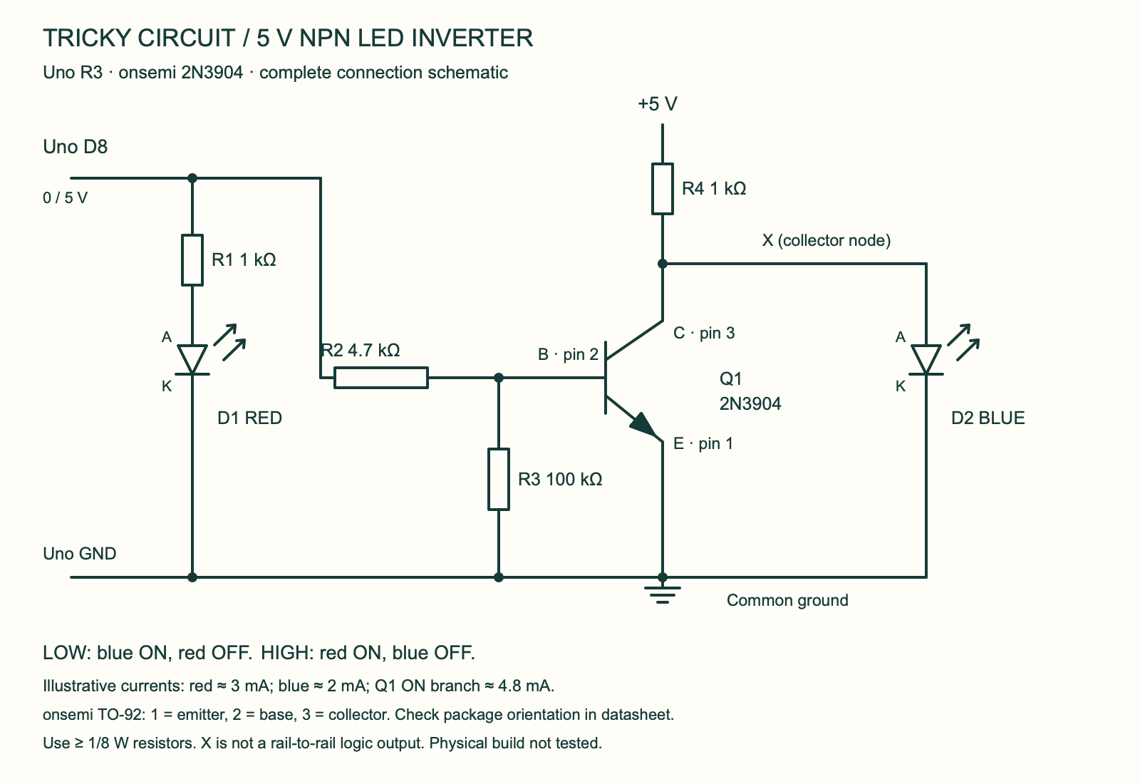
- Use an Arduino Uno R3 with 5 V logic, one 2N3904 transistor, one red LED, one blue LED, two 1 kΩ resistors, one 4.7 kΩ resistor and one 100 kΩ resistor.
- NPN describes the transistor’s n-type, p-type and n-type semiconductor regions. Its terminals are base (B), collector (C) and emitter (E). This schematic uses the onsemi 2N3904 in the TO-92 package: pin 1 is emitter, pin 2 base and pin 3 collector. Check the package orientation in its datasheet; do not assume another manufacturer uses the same pin order.
- The 4.7 kΩ resistor limits base current; the 100 kΩ resistor keeps the base low if the control wire is disconnected. Each 1 kΩ resistor limits current in its LED path.
Wire the two branches
| Connection | Purpose |
|---|---|
| Uno D8 → 1 kΩ → red LED anode; red cathode → GND | Red follows the input |
| D8 → 4.7 kΩ → B; 100 kΩ between B and E | Base drive and pull-down |
| E → GND; Uno GND → circuit GND | Common return |
| +5 V → 1 kΩ → node X; node X → C and blue LED anode | Required supply path for the blue LED |
| Blue LED cathode → GND | Inverted indicator |
The collector resistor is essential. A blue LED connected only between collector and ground has no source of current when the transistor is off. In this circuit the collector resistor also serves as the blue LED’s current-limiting resistor; do not replace it with a wire.
Understand the two states
| D8 | Transistor | Red | Blue |
|---|---|---|---|
| LOW | Off | Off | On |
| HIGH | On | On | Off |
Using illustrative forward voltages of 2 V for red and 3 V for blue, their currents are about (5 − 2)/1000 = 3 mA and (5 − 3)/1000 = 2 mA. When the transistor is on, its collector branch carries roughly (5 − 0.2)/1000 = 4.8 mA instead. Base current is about (5 − 0.7)/4700 = 0.91 mA. Actual voltages depend on the parts; the chosen resistor values keep this demonstration at a few milliamps.
Node X rises only to approximately the blue LED’s forward voltage. It is an indicator node, not a guaranteed 5 V digital output for another logic chip.
Blink the input
const byte INPUT_PIN = 8;
void setup() {
  digitalWrite(INPUT_PIN, LOW);
  pinMode(INPUT_PIN, OUTPUT);
}
void loop() {
  digitalWrite(INPUT_PIN, HIGH); delay(1000);
  digitalWrite(INPUT_PIN, LOW);  delay(1000);
}
Bench checks
- With power disconnected, check that neither LED is reversed and verify the transistor’s actual pin order.
- Start with D8 LOW: expect blue on and red off. Measure node X relative to ground.
- Set D8 HIGH: expect red on and blue off; node X should fall close to ground.
- If blue never lights, check the mandatory collector resistor. If both stay on, inspect base, emitter and collector connections.
Before calling this a tested build
This is a documented bench experiment. The wiring and calculations have been reviewed; this build has not yet been tested on physical hardware. Record the exact part marking, supply voltage, measurements and a clear wiring photo when you try it.
Sources and next steps
Continue with the Tricky Circuit electronics lessons.