🔹 How It Works:
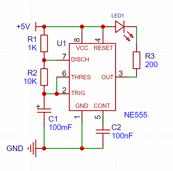
In astable mode, the NE555 continuously switches between HIGH and LOW states, generating a square wave signal. This makes the LED blink at a set frequency.
🔧 Components Needed:
- NE555 Timer IC (1x)
- Resistors:
- 1kΩ (1x)
- 10kΩ (1x)
- Capacitor:
- 10µF (electrolytic) (1x)
- LED (1x)
- Power supply (5V or 9V battery)
- Breadboard & jumper wires
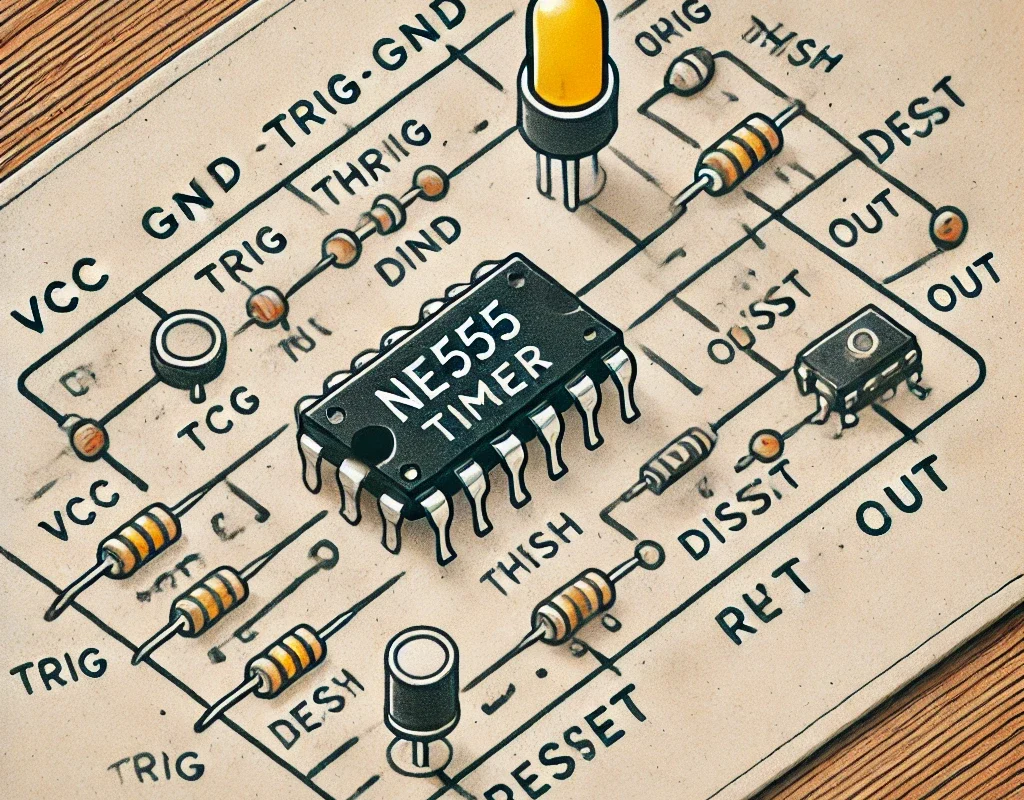
⚡ Circuit Diagram:
🛠 How to Build:
- Connect Power:
- VCC (Pin 8) → 5V or 9V power supply
- GND (Pin 1) → Ground (0V)
- Set Up the Timing Components:
- 1kΩ resistor (R1) between VCC (Pin 8) and Discharge (Pin 7)
- 10kΩ resistor (R2) between Discharge (Pin 7) and Threshold (Pin 6)
- 100µF capacitor (C1) between Threshold (Pin 6) and Ground (GND)
- 100nF capacitor (C2) between Control (Pin 5) and Ground (GND)
- Jumper between Threshold (Pin 6) and Trigger (Pin 2)
- Jumper between Reset (Pin 4) and VCC (Pin 8)
- Connect the Output:
- LED (with 200Ω resistor) connects from Output (Pin 3) to Ground (GND)
- Power the Circuit:
- When powered on, the LED will blink continuously at a frequency set by R1, R2, and C1.