
Diodes · Forward bias · Bench measurements
Warm a small silicon diode and its forward voltage changes. Changing the test current can shift that same reading even if the diode stays at room temperature. This experiment keeps the current matched across two dry temperature plateaus, then repeats the comparison at a second current. You measure the current with a known resistor and estimate how much of the apparent voltage change a residual current mismatch could explain.
What the number means. This fixture measures the voltage of one Vishay 1N4148-TAP against the nearby spreader temperature over a small interval. The thermocouple touches the spreader assembly next to the diode. A different mounting method or a calibrated junction-temperature system can give a different result. All values in the worked capture are synthetic.
Wire the diode, resistor and two independent voltage meters
Use the Vishay 1N4148-TAP in the axial glass DO-35 package. Identify the banded cathode on the physical part. It connects to the supply return. The unbanded anode connects to R1. The Vishay data sheet plots typical forward voltage against junction temperature at both 0.1 mA and 1 mA. The separate 1 V maximum in the electrical table is specified at 10 mA and 25 °C ambient. This experiment compares two much smaller currents and uses its own input screens.
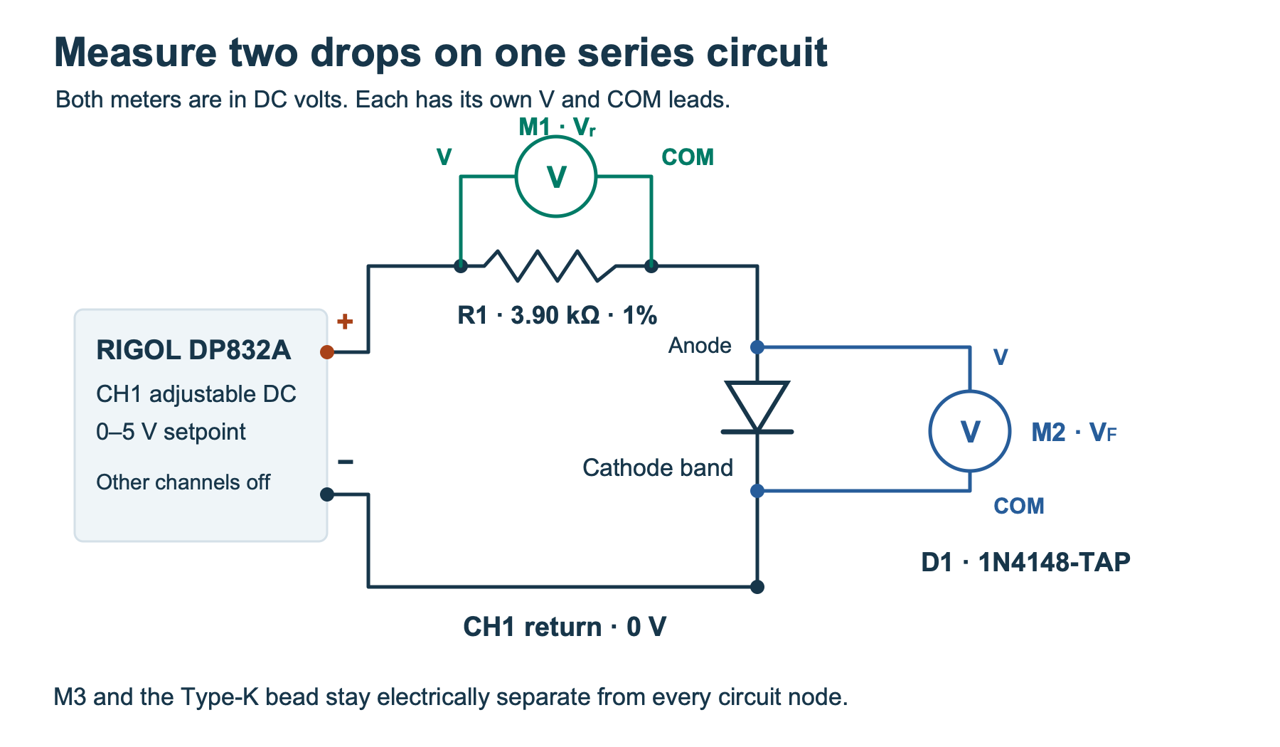
tricky-circuit-campaigns145-150/batch-015/packages/1n4148-forward-voltage-temperature/diode-fixture.svg). · Full-size PNG- Supply. Use RIGOL DP832A channel 1 with its housing intact. Start at zero with the output disabled, leave the other channels off, and work below a 5.0 V programmed setpoint. Set the channel’s current limit to 10 mA and its overvoltage protection to 5.0 V. The overvoltage setting is a backup and has a specified error. Read the actual drops with the separate meters. The DP832A has 1 mV programming increments on CH1.
- Series resistor. Use a 3.90 kΩ ±1% Vishay MRS25, for example MRS25000C3901FCT00, rated 0.6 W at 70 °C under the data sheet conditions. Measure R1 out of circuit and keep it away from the warm plate. Leave it in series throughout. At 5.0 V and its 3.861 kΩ lower bound, the resistor branch is limited to about 1.295 mA and 6.48 mW even with a short at D1. This calculation refers to an actual 5.0 V terminal voltage.
- Meters. Use two separate battery-operated Fluke 87V MAX meters in DC voltage mode, each with the red lead in V and the black lead in COM. M1 goes across R1, red at CH1 positive and COM at the R1–D1 junction. M2 goes across D1, red at the junction and COM at CH1 negative. Keep the same meter on each pair of points and use the same fixed 6 V DC range for room and warm. Keep both meter bodies near room temperature.
Use an insulating support. Keep the diode and wiring clear of any exposed metal on the fixture. Verify forward polarity with output disabled. Never replace the series resistor with a wire or use a meter’s current terminals across the supply. The two meter COM leads must remain electrically independent. An oscilloscope with common grounded clips cannot substitute for them with this exact connection.
Set up a dry thermal mount
Place a small, smooth aluminum spreader on an insulated support. Cover the working spot with thin electrical-insulating polyimide tape. Tape the glass body against the covered spot and secure the leads at a distance so they do not lift the body. Keep the bare lead ends insulated and off the plate. Place a Fluke 80BK-A Type-K thermocouple bead beside the glass, within about 5 mm, under a separate strip of tape so it is held against the film. Use a third Fluke 87V MAX in its temperature mode. Keep the thermocouple electrically separate from every test node. With the supply disconnected, check that the diode circuit and the probe bead have no continuity to the spreader or to each other.
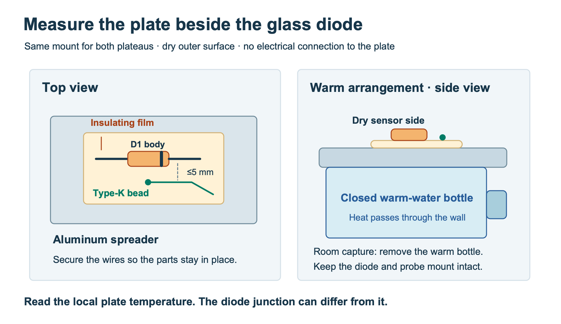
tricky-circuit-campaigns145-150/batch-015/packages/1n4148-forward-voltage-temperature/dry-plate.svg).For the warm plateau, fill a closed flat-sided container with roughly 42–48 °C tap water away from the bench, close it, dry the exterior and put it on a stable tray. Rest the spreader against its dry outside surface and leave the diode and bead mounted as before. Keep the power supply and its mains connection away from the tray. Stop if the container leaks or if moisture reaches the fixture. Use the bead’s actual reading for both plateaus. The water temperature, room air and bead are different measurements.
Allow the plate to settle after mounting or changing current. Aim for 18–27 °C at room and 34–45 °C on the warm plate, with at least a 10 °C median difference for each current. Before recording a plateau, wait until the bead reading drifts by no more than about 0.3 °C over 30 s. Hold the full set of six readings to 0.8 °C of spread. If the bottle cools too quickly, repeat the warm preparation, wait again and start a new set.
Match the current from the measured drops
The resistor voltage should be near 0.390 V at 100 µA and 3.900 V at 1 mA. Current through the meter across R1 also enters the diode node. Current through the meter across D1 leaves the node without passing through the diode. The two meters each have approximately 10 MΩ input resistance in DC volts. Calculate the current from their measured positive drops and the actual R1.
ID = VR(1/R1 + 1/RM1) − VF/RM2
With the nominal resistor and two 10 MΩ meters, 0.390 V and 0.530 V give 99.986 µA. At 3.900 V and 0.646 V, the same calculation gives 1000.325 µA. These are arithmetic examples. Treat the input resistances as nominal unless you have separate measurements.
- With the diode at the room plateau, enable CH1 and start low. Raise the output slowly while watching both readings. Begin near 0.9 V for 100 µA or 4.5 V for 1 mA, and use the measured drops to adjust. Stay under a 5.0 V programmed setting and stop if the measured sum of both drops exceeds 5.05 V. Stop if the diode has unexpected polarity or if the meters are overrange.
- Record three settled triples at each current. Each row gets the plate temperature, the resistor voltage and the diode voltage. Keep all three readings close in time. Adjust the programmed voltage again after warming or cooling the plate. The same supply setting can produce a different diode current.
- Use a ±1% measured current window for each row and keep the two plateau medians within 0.5% of the nominal target. Use the same meter ranges and resistor throughout. If your meter resolution, noise or source stability makes matching impractical, record that limitation and retain the failed check.
- After the warm run, disable CH1, remove the bottle and let the mounted diode and bead settle again at room temperature. At both currents, compare new readings with the first room set. A disagreement beyond repeatability and the measured temperature difference suggests fixture or contact drift. Record the return check separately in your bench notes. The Python tool expects exactly the first room and warm sets.
Compare the two temperature slopes
Take the median forward voltage and median plate temperature within each group of three, then calculate a separate room-to-warm slope at each current.
s = (VF,warm − VF,room) / (Tplate,warm − Tplate,room)
To see whether the residual current mismatch is large enough to matter, the analyzer also compares the two current groups at each plateau. It takes the larger of the two observed voltage chords per natural-log current interval and multiplies that value by the absolute natural log of the warm-to-room current ratio. This is an approximate voltage scale for current mismatch. The two currents are about a decade apart, so a chord can differ from the slope right beside either test current. Keep this estimate separate from the measured temperature slope and its uncertainty.
C = (VF,high − VF,low) / ln(Ihigh/Ilow)
ΔVmismatch ≈ max(Croom, Cwarm) × |ln(Iwarm/Iroom)|
The bundled synthetic readings use plate medians of 22.0 and 40.0 °C. The slopes below are calculated from the shipped CSV. An actual diode can give different values.
| Current target | Room → warm current | Room → warm voltage | Slope | Mismatch scale |
|---|---|---|---|---|
| 100 µA | 100.0 → 100.1 µA | 0.530 → 0.491 V | −2.17 mV/°C | 0.053 mV |
| 1 mA | 1000 → 1001 µA | 0.646 → 0.612 V | −1.89 mV/°C | 0.053 mV |
For a normal-resolution 6 V DC range, the meter specifies a 1 mV display step and ±(0.05% of reading + one count) under the manual’s conditions. The temperature channel’s specified accuracy excludes the thermocouple. At room and warm, the meter and the supplied probe have errors on the order of degrees Celsius, and the local plate-to-junction gradient is unmeasured. Three repeated readings help reveal instability. They leave systematic sensor error and thermal contact error in the result. Compare the size of any apparent difference in slopes with those uncertainties before interpreting it.
Complete Python analyzer
Use the blank worksheet (ZIP; file: tricky-circuit-campaigns145-150/batch-015/packages/1n4148-forward-voltage-temperature/observations-blank.csv) and fill all 12 numeric rows. The header is plateau,target_ua,repeat,plate_c,series_v,forward_v. Use room and warm, targets 100 and 1000, and repeats 1–3. The experiment archive (ZIP; file: tricky-circuit-campaigns145-150/batch-015/packages/1n4148-forward-voltage-temperature/experiment-tests-v1.zip) includes the code, synthetic capture, exact JSON output, editable drawings and tests. Run python3 diode_temp.py synthetic-captures.csv --kind synthetic --series-ohms 3900. For your own data use --kind observed and the measured resistor value. Leave both meter input resistance arguments at 10 MΩ unless you have independently measured them.
The script checks complete finite input, the electrical and thermal screens, current matching, and a 3 mV maximum forward-voltage spread within each repeat group. If a plateau drifts or the voltage fails to rise with current at one temperature, it withholds both slopes. A pair-specific failure withholds that pair’s slope. A failed gate leaves the raw medians in the report so you can see which reading needs attention. The tests exercise the program on a computer. Any bench result needs measurements from the actual fixture.
#!/usr/bin/env python3
"""Compare forward voltage across two temperature plateaus at matched currents."""
import argparse
import csv
import json
import math
from pathlib import Path
from statistics import median

HEADER = ['plateau', 'target_ua', 'repeat', 'plate_c', 'series_v', 'forward_v']
PLATEAUS = {'room': (18, 27), 'warm': (34, 45)}
TARGETS = (100, 1000)
REPEATS = (1, 2, 3)
EPS = 1e-8


def read_capture(path, resistor, series_meter, diode_meter):
    groups = {(p, n): {} for p in PLATEAUS for n in TARGETS}
    with path.open(encoding='utf-8-sig', newline='') as f:
        reader = csv.reader(f, strict=True)
        if next(reader, None) != HEADER:
            raise ValueError('expected header ' + ','.join(HEADER))
        for row in reader:
            line = reader.line_num
            if len(row) != len(HEADER):
                raise ValueError(f'line {line}: expected six fields')
            label, target, repeat = row[0], int(row[1]), int(row[2])
            if (label, target) not in groups or repeat not in REPEATS:
                raise ValueError(f'line {line}: unknown plateau, target or repeat')
            group = groups[label, target]
            if repeat in group:
                raise ValueError(f'line {line}: duplicate repeat')
            t, vr, vf = map(float, row[3:])
            if not all(map(math.isfinite, (t, vr, vf))):
                raise ValueError(f'line {line}: measurements must be finite')
            low, high = PLATEAUS[label]
            if not low <= t <= high:
                raise ValueError(f'line {line}: temperature outside the {label} screen')
            if vr <= 0 or not .25 <= vf <= 1.10 or vr + vf > 5.05 + EPS:
                raise ValueError(f'line {line}: voltage outside the fixture screen')
            i = 1e6 * (vr * (1/resistor + 1/series_meter) - vf/diode_meter)
            group[repeat] = (t, vf, i)
    if any(len(group) != len(REPEATS) for group in groups.values()):
        raise ValueError('expected all 12 capture rows')
    return {key: list(value.values()) for key,value in groups.items()}


def summary(rows):
    temperatures, volts, currents = zip(*rows)
    return {
        'plate_c': median(temperatures),
        'forward_v': median(volts),
        'diode_ua': median(currents),
        'span_forward_mv': 1000 * (max(volts) - min(volts)),
        'min_ua': min(currents),
        'max_ua': max(currents),
    }


def report(data, kind):
    summaries = {p:{n:summary(data[p,n]) for n in TARGETS} for p in PLATEAUS}
    temperature_samples = {p:[row[0] for n in TARGETS for row in data[p,n]] for p in PLATEAUS}
    stability = all(max(a)-min(a) <= .8 + EPS for a in temperature_samples.values())
    chords = {}
    for plateau in PLATEAUS:
        lo,hi = (summaries[plateau][n] for n in TARGETS)
        if hi['diode_ua'] > lo['diode_ua'] > 0 and hi['forward_v'] > lo['forward_v']:
            chords[plateau] = 1000 * (hi['forward_v']-lo['forward_v']) / math.log(hi['diode_ua']/lo['diode_ua'])
    checks = {
        'plateau_stability': stability,
        'forward_voltage_rises_with_current': len(chords)==len(PLATEAUS),
    }
    comparison = {}
    for n in TARGETS:
        room, warm = (summaries[p][n] for p in PLATEAUS)
        delta_t = warm['plate_c'] - room['plate_c']
        delta_v = 1000 * (warm['forward_v'] - room['forward_v'])
        mismatch_pct = 100 * abs(warm['diode_ua'] - room['diode_ua']) / n
        pair = {
            'target_window': all(g['min_ua'] >= .99*n-EPS and g['max_ua'] <= 1.01*n+EPS
                                 for g in (room,warm)),
            'matched_current': mismatch_pct <= .50 + EPS,
            'repeat_voltage_spread': all(g['span_forward_mv'] <= 3 + EPS for g in (room,warm)),
            'temperature_separation': delta_t >= 10 - EPS,
        }
        valid = all(checks.values()) and all(pair.values())
        comparison[n] = {'checks':pair,'room_ua':room['diode_ua'],'warm_ua':warm['diode_ua'],
                         'mismatch_pct_of_target':mismatch_pct,'delta_plate_c':delta_t,
                         'delta_forward_mv':delta_v,'slope_mv_per_c':delta_v/delta_t if valid else None,
                         'mismatch_scale_mv':max(chords.values())*abs(math.log(warm['diode_ua']/room['diode_ua']))
                         if valid else None}
    return {
        'kind':kind,'state':'qualified' if all(x['slope_mv_per_c'] is not None for x in comparison.values())
        else 'investigate','checks':checks,'groups':summaries,'comparison':comparison,
        'measured_chord_mv_per_log_current':chords,
        'scope':'Plate-temperature slopes and approximate mismatch scale for this fixture.',
    }


def main():
    ap = argparse.ArgumentParser(description=__doc__)
    ap.add_argument('csv', type=Path)
    ap.add_argument('--kind', choices=('synthetic','observed'), required=True)
    ap.add_argument('--series-ohms', type=float, required=True)
    ap.add_argument('--series-meter-megohms', type=float, default=10)
    ap.add_argument('--diode-meter-megohms', type=float, default=10)
    a = ap.parse_args()
    if not 3861 <= a.series_ohms <= 3939:
        ap.error('expected a measured 3.90 kΩ ±1% series resistor')
    if not all(8 <= r <= 12 for r in (a.series_meter_megohms,a.diode_meter_megohms)):
        ap.error('expected both DC meter input resistances near 10 MΩ')
    try:
        result = report(read_capture(a.csv,a.series_ohms,1e6*a.series_meter_megohms,
                                     1e6*a.diode_meter_megohms),a.kind)
    except (ValueError, OSError, UnicodeError, csv.Error) as exc:
        ap.error(str(exc))
    print(json.dumps(result,indent=2,allow_nan=False))


if __name__ == '__main__':
    main()
Challenge
Your diode reads 33 mV lower on the warm plate. You left the same supply voltage set at both temperatures. With a 3.90 kΩ series resistor, how much does that forward-voltage change shift the current before meter loading? Is that small enough to pass the 100 µA pair screen?
Check your reasoning
The resistor gets about 33 mV more, so the current rises by 0.033 V / 3900 Ω, or about 8.46 µA. That is about 8.5% of the 100 µA target, well beyond the 0.5% pair screen. Lower the supply setpoint at the warm plateau until the measured current matches the room result. The actual readings and the meter-loading correction determine whether it passes.
Primary sources and related reading
- Vishay 1N4148, document 81857 rev. 1.6, exact package and polarity, Figure 1 temperature curves and Figure 2 current-voltage curves.
- Vishay MRS25 series data sheet, rated dissipation, value coding and tolerance.
- RIGOL DP800 data sheet, the separate DP832A specifications for CH1 resolution and protection.
- Fluke 87V MAX user manual and Fluke 80BK-A probe specifications, nominal input loading and temperature measurement conditions.
- Measure a diode path through an unpowered rail for a different use of the same type of switching diode.
Download the complete reader files (ZIP): full programs, blank observation worksheets, original editable SVG/PNG diagrams and selected support files for 1n4148-forward-voltage-temperature. Inline main programs remain complete; this download is supplementary.