A magnet moves away from a door sensor and returns. Your program reads the same LOW level before and after. Perhaps nothing moved—or perhaps the sensor slept through the excursion. Build a small magnetic-switch fixture and separate the sensor’s internal sample interval from the speed of the program reading its output.
This is an original design and host-software exercise, not a measured prototype. The code has host tests; the Pico firmware, magnetic fixture and waveforms have not been executed or measured here. No alarm, lock or unattended control is implemented.
1. Follow the information through three stages
A Hall-effect switch responds to magnetic flux, the magnetic field passing through its sensing element. This part measures the field at intervals and holds its electrical output between measurements. The Pico then observes that held output. Physical movement, the sensor’s magnetic measurement, and the program’s input read are three different events.
In a common door arrangement, a magnet near the sensor produces LOW and moving it sufficiently far away produces HIGH. These are qualified positions for one installation, not a universal definition of an open or closed door. A detached magnet, damaged wire or wrong alignment can produce the same electrical reading as ordinary movement. Our log therefore uses electrical levels and observed_edges; it deliberately has no trusted current_door_state or physical-opening count.
2. Read the complete part number
U1 is Texas Instruments DRV5032FCDBZR, an omnipolar switch in the three-pin DBZ Small Outline Transistor (SOT-23) package. Omnipolar means that either magnetic polarity can activate it when the relevant field component is strong enough. The component perpendicular to the top of the package matters; turning a magnet sideways can change the result. Mount U1 on a passive adapter and continuity-check its actual package pads. A printed adapter label is not proof of pin routing.
The current SLVSDC7H datasheet, revision H dated December 2024, identifies FC as an open-drain, nominal 20 Hz version. An open-drain output pulls LOW or releases the wire; it needs an external pull-up resistor. The exact-part product-card headline says 5 Hz, but the variant and electrical tables say 20 Hz. This lesson follows those tables. The similar FB is a 5 Hz push-pull version and is not the part fitted here.
Hertz (Hz) means samples per second. For FC, the listed magnetic-sampling period is 27 ms minimum, 50 ms typical and 75 ms maximum under the datasheet conditions. The output is latched between updates: “latched” here means held until the next internal update, not a permanent memory of every opening. A faster Pico loop cannot recover a magnetic excursion that never changed OUT.
Use one original RP2040 Raspberry Pi Pico with official RPI_PICO MicroPython 1.26.0, selected for reproducibility. The symbols in this lesson include volts (V), millivolts (mV), microamperes (µA), milliamperes (mA), milliwatts (mW), kilohms (kΩ), nanofarads (nF), milliseconds (ms), microseconds (µs) and millitesla (mT), a magnetic-flux-density unit.
3. Wire one supply domain and one input
| Part or net | Exact connection and purpose |
|---|---|
| Power | Pico 3V3_OUT, physical pin 36 → U1 VCC pin 1 and the top of R1. Power the Pico only through its Universal Serial Bus (USB) connector. |
| Return | Pico GND, physical pin 38 → U1 GND pin 3 and the ground side of C1. All instrument returns for this common-domain fixture use this ground. |
| Signal | U1 OUT pin 2 → Pico GP16, physical pin 21. GP16 is a general-purpose input/output (GPIO) configured only as an input. |
| R1 | Vishay MRS25000C1002FCT00, 10 kΩ ±1%, between 3V3 and OUT. Place R1 at the Pico input node; it establishes HIGH when U1 releases the output. |
| C1 | 100 nF nonpolar X7R ceramic, rated at least 10 V, directly across U1 VCC 1 and GND 3. This is a local supply bypass, not an output filter. |
| Magnet fixture | One identified magnet fixed to a nonmagnetic slider, with near/far hard stops and a ruler. Record maker/model, dimensions, orientation and both positions; no fixed activation distance is asserted. |
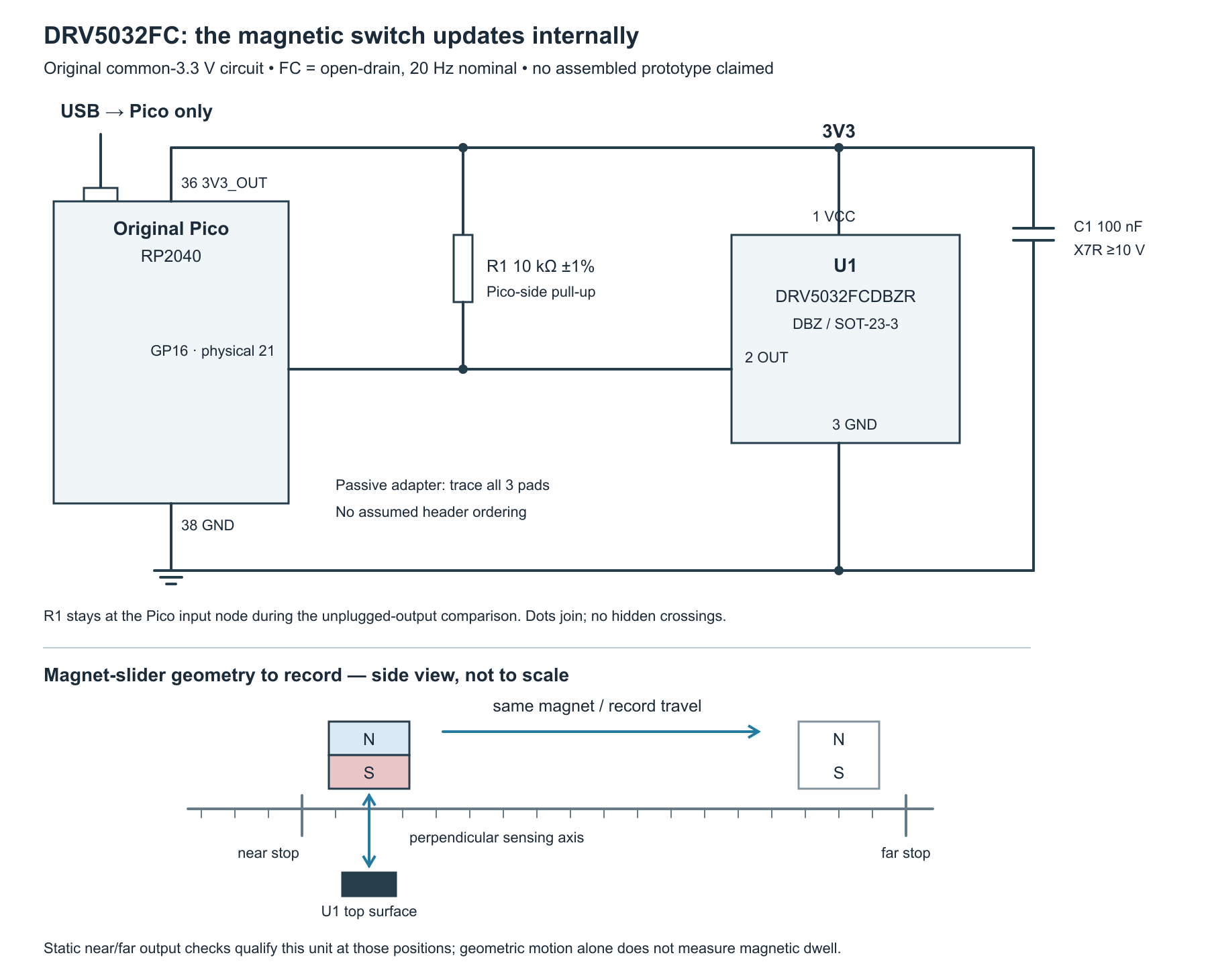
tricky-circuit-campaigns87-92/batch-010/packages/drv5032-door-blind-interval/drv5032-functional.svg).U1 operates from 1.65–5.5 V, but this fixture uses the Pico’s nominal 3.3 V throughout. Do not attach a 5 V pull-up, an externally powered signal, or a second positive supply. U1’s absolute output limits include its own supply, and the Pico input is not a 5 V input. Power OFF before changing any wire or adapter orientation. Do not connect a test generator in parallel with the sensor’s OUT.
At the RP2040’s specified 3.3 V input/output supply condition, the input HIGH requirement is at least 2.0 V and LOW at most 0.8 V. TI specifies an output LOW maximum of 0.3 V at a 1 mA sink test condition. Our nominal pull-up current is smaller, but still measure the real loaded LOW, HIGH and edges at GP16; a wiring diagram does not qualify a waveform. Keep leads short and reject unknown extra pull-ups or filtering.
4. The pull-up can cost more than the sensor
Assumed rail:                3.3 V
R1 current while OUT is LOW:  I = 3.3 / 10000 = 330 µA
R1 power while OUT is LOW:    P = 3.3² / 10000 = 1.089 mW
At R1's -1% limit:           I = 3.3 / 9900 ≈ 333 µA
Nominal magnetic period:     T = 1 / 20 Hz = 50 ms
The FC datasheet gives a typical sensor-only average supply current of 1.6 µA at 3 V, with a 3.5 µA maximum in that table row. This is not a specification at exactly 3.3 V and does not include R1, the Pico, USB or instruments. A normally LOW installation continuously conducts through R1. The illustrative 330 µA branch is over two hundred times that 3 V typical sensor-current figure. Do not turn a low sensor-current headline into a battery-life claim for the complete fixture.
A much larger pull-up could reduce the LOW current, but would also interact with leakage, input current and wire capacitance. It is a different electrical design that needs its own edge and logic-level qualification. No alternate resistor is silently substituted in this experiment.
5. Qualify the magnetic positions before timing them
The operate threshold, BOP, is the field needed to activate the switch; the release threshold, BRP, is the smaller field at which it releases. Their separation is magnetic hysteresis: the previous state affects the switching boundary. FC’s listed operate magnitude reaches 4.8 mT and its release magnitude can be as low as 0.5 mT. A design claiming magnetic margin needs the appropriate field beyond those extremes under the actual conditions, rather than a guessed distance.
First hold the near stop for a full second, then the far stop for a full second, and repeat both directions. Check LOW near and HIGH far at the terminal and record the real geometry. This confirms the static behavior of this unit and fixture at the time of the test. It does not establish a calibrated field profile or a minimum reliable transit time.
A ruler and sufficiently fast video can describe a geometric absence from a marked position. They do not independently prove how long the field at the silicon was below the release threshold. A quantitative magnetic-dwell claim needs a separately qualified field measurement and time reference. Keep an unqualified quick-pass result labelled “geometric excursion; magnetic dwell unknown.” Never invent an exact millisecond field pulse from a hand movement.
6. Compare two sampling phases
The model begins with a qualified magnet-near LOW state. It gives the sensor ideal point samples every 50 ms and assumes a magnetic absence from 10 ms up to, but not including, 30 ms. At sample times 0, 50 and 100 ms, no sample lands inside that interval, so the ideal output remains LOW. Shift the sample phase to 20 ms: one sample sees absence and the held output becomes HIGH from 20 to 70 ms—even though the assumed absence ended at 30 ms.
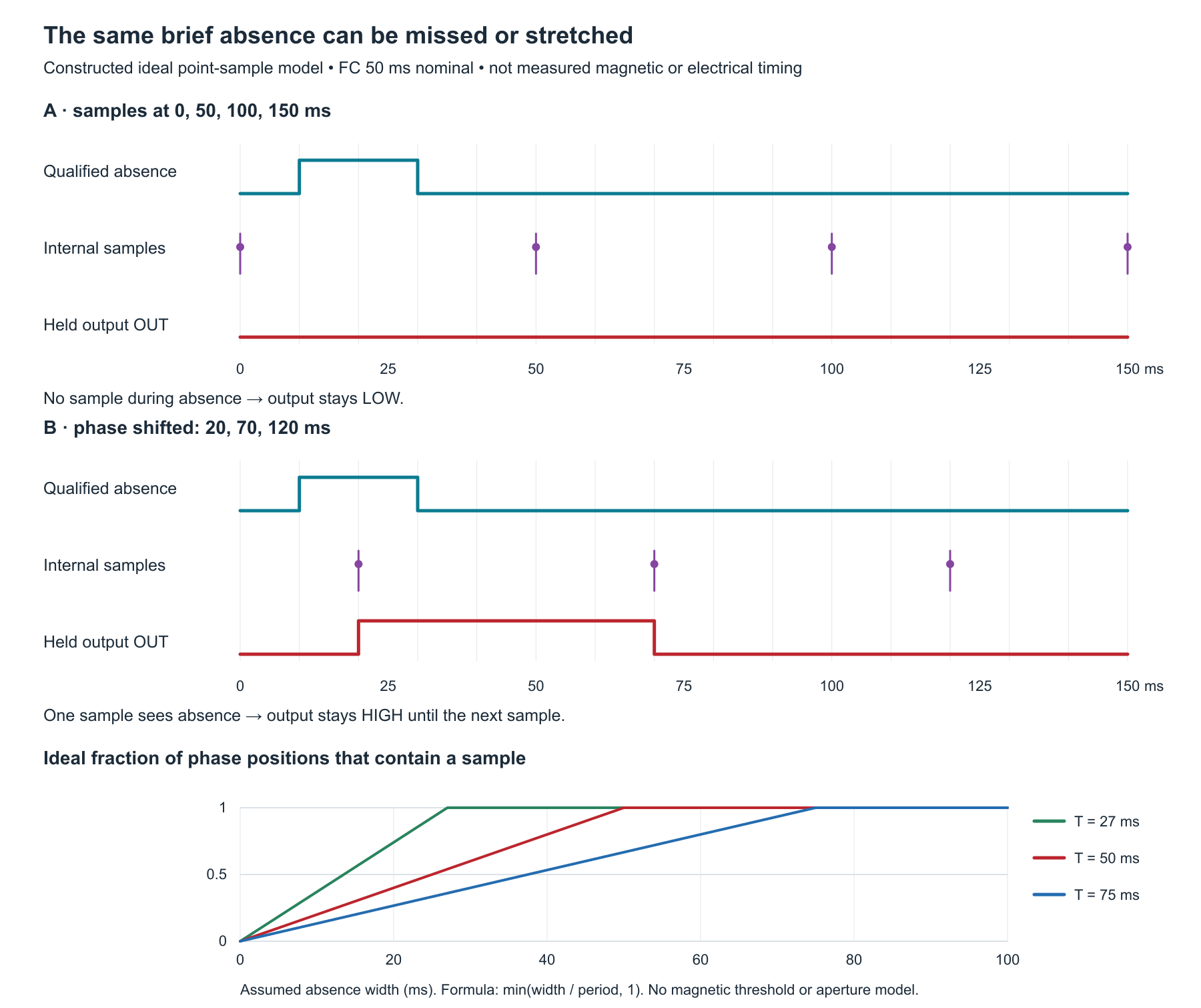
tricky-circuit-campaigns87-92/batch-010/packages/drv5032-door-blind-interval/drv5032-sampling.svg).Ideal phase coverage for an absence of width w and period T:
covered fraction = min(w / T, 1)
For w = 20 ms, T = 50 ms: 20 / 50 = 0.40
For T = 27 ms: 20 / 27 ≈ 0.741
For T = 75 ms: 20 / 75 ≈ 0.267These are fractions of possible phases in the deliberately simplified model. They become probabilities only with an additional uniform-random-phase assumption. They are not measured detection rates. The real sensor has magnetic thresholds, hysteresis, an active interval, period variation and electrical propagation. The model omits those effects and is not a guarantee that a given door movement will be detected. It makes the information loss visible without disguising a calculation as a bench result.
7. What the observer records and rejects
The collector requests a 1 ms wait between input reads and rejects an observed service gap over 10 ms. The wait is not a guaranteed real-time schedule, and it does not change U1’s internal sampling. The first accepted level establishes a baseline; it is not counted as an edge. A later changed level creates a window from the preceding read’s start to the new read’s end. The electrical transition lies somewhere in that window if the read/clock assumptions hold; the window is not the time of a magnetic sample or a physical opening.
A five-second session retains at most 64 changed-level windows and prints only after capture has closed. Invalid input values, input exceptions, backward clocks, excessive observed gaps, edge overflow and an exhausted step limit raise an exception instead of returning a partial success. A final read that finishes at or after the deadline is excluded. An unchanged input is retained as an observation, but no observed edges does not prove no motion, correct wiring or sensor health.
The modular tick calculation is valid only when the true interval is shorter than half the tick counter’s period. A completely unobserved wrap can alias the old value; no software guard here can diagnose that. Keep the documented short-service-gap assumption, and use independent instruments when qualifying the physical behavior. The finite step limit also terminates a loop whose clock stops advancing.
At exit, the program attempts to leave GP16 as an input with its internal pulls disabled. That is not a sensor power-OFF command: the sensor remains connected to 3V3. An already printed CLOSED log describes the completed observation interval, not later cleanup success or current health. Console or cleanup failures propagate as exceptions.
8. Complete MicroPython program
Save this complete program (ZIP; file: tricky-circuit-campaigns87-92/batch-010/packages/drv5032-door-blind-interval/drv5032-door-blind-interval.py) as drv5032-door-blind-interval.py on the Pico, not as main.py. From the Read-Evaluate-Print Loop (REPL), MicroPython’s interactive prompt, use this three-line block once:
ns = {"__name__": "door92"}
exec(open("drv5032-door-blind-interval.py").read(), ns)
ns["main"]()
The program uses the selected version’s Pin and time application programming interfaces (APIs). Its 100 ms startup allowance is an application delay; it does not measure or certify the supply waveform. The model functions are available in the same file but are not used to replace real input readings.
"""DRV5032FC / original Pico / MicroPython 1.26.0 teaching experiment.

Actual collector: finite observations of a latched electrical output, never
counts of physical openings. Ideal model: point samples of a threshold-qualified
magnetic absence; not a model of real magnetic fields, aperture or latency.
No target execution, built prototype or physical measurements are claimed.
"""

class CaptureFault(RuntimeError):
    pass


def integer(value, name, low, high):
    if type(value) is not int or not low <= value <= high:
        raise ValueError(name)
    return value


class TicksElapsed:
    """Unwrap ticks only under the documented short-service-gap assumption."""
    def __init__(self, ticks_ms, ticks_diff, max_gap_ms=1000):
        self.ticks_ms, self.ticks_diff = ticks_ms, ticks_diff
        self.max_gap = integer(max_gap_ms, "max_gap_ms", 1, 10000)
        self.previous = ticks_ms()
        if type(self.previous) is not int:
            raise CaptureFault("CLOCK_TYPE")
        self.elapsed, self.failed = 0, False

    def now(self):
        if self.failed:
            raise CaptureFault("CLOCK_FAULT")
        try:
            raw = self.ticks_ms()
            if type(raw) is not int:
                raise CaptureFault("CLOCK_TYPE")
            delta = self.ticks_diff(raw, self.previous)
            if type(delta) is not int or not 0 <= delta <= self.max_gap:
                raise CaptureFault("CLOCK_GAP")
            self.previous = raw
            self.elapsed += delta
            return self.elapsed
        except BaseException:
            self.failed = True
            raise


def collect(read_pin, now_ms, sleep_ms, duration_ms=5000, interval_ms=1,
            max_gap_ms=10, step_limit=12000, edge_limit=64):
    """Return one closed observation log, or raise without a partial success.

    Edge windows bound changes between two observed input levels. They are
    not sensor magnetic-sampling timestamps or physical-opening durations.
    No console I/O occurs inside capture. A late final read is not accepted.
    """
    integer(duration_ms, "duration_ms", 1, 10000)
    integer(interval_ms, "interval_ms", 1, 100)
    integer(max_gap_ms, "max_gap_ms", interval_ms, 1000)
    integer(step_limit, "step_limit", 1, 20000)
    integer(edge_limit, "edge_limit", 1, 256)
    start = now_ms()
    if type(start) is not int:
        raise CaptureFault("CLOCK_TYPE")
    previous_time = start
    last_before = last_after = None
    initial = last_level = None
    polls, edges = 0, []
    reason = "TIME_LIMIT"
    for unused in range(step_limit):
        before = now_ms()
        if type(before) is not int or before < previous_time:
            raise CaptureFault("CLOCK_ORDER")
        if before - previous_time > max_gap_ms:
            raise CaptureFault("POLL_GAP")
        if before - start >= duration_ms:
            break
        level = read_pin()
        after = now_ms()
        if type(after) is not int or after < before:
            raise CaptureFault("CLOCK_ORDER")
        if after - before > max_gap_ms:
            raise CaptureFault("READ_GAP")
        if last_after is not None and after - last_after > max_gap_ms:
            raise CaptureFault("POLL_GAP")
        if type(level) is not int or level not in (0, 1):
            raise CaptureFault("INPUT_LEVEL")
        if after - start >= duration_ms:
            reason = "TIME_LIMIT_DURING_READ"
            break
        if initial is None:
            initial = level
        elif level != last_level:
            if len(edges) >= edge_limit:
                raise CaptureFault("EDGE_LIMIT")
            edges.append({"from": last_level, "to": level,
                          "earliest_ms": last_before - start,
                          "latest_ms": after - start})
        last_before, last_after = before, after
        last_level, previous_time = level, after
        polls += 1
        sleep_ms(interval_ms)
    else:
        raise CaptureFault("STEP_LIMIT")
    if polls == 0:
        raise CaptureFault("NO_ACCEPTED_OBSERVATIONS")
    return {"status": "CLOSED_OUTPUT_OBSERVATIONS", "end_reason": reason,
            "polls": polls, "initial_level": initial, "last_level": last_level,
            "last_observation_at_ms": last_after - start,
            "observed_edges": len(edges), "edge_windows": edges,
            "physical_openings": None, "current_door_state": None}


def phase_hit(start_us, width_us, period_us, phase_us):
    """Ideal periodic POINT samples, with absence interval [start, start+width)."""
    integer(start_us, "start_us", 0, 2000000)
    integer(width_us, "width_us", 0, 2000000)
    integer(period_us, "period_us", 1, 1000000)
    integer(phase_us, "phase_us", 0, period_us - 1)
    return (phase_us - start_us) % period_us < width_us


def phase_coverage(width_us, period_us):
    """Fraction of ideal phase positions, NOT measured detection probability."""
    integer(width_us, "width_us", 0, 2000000)
    integer(period_us, "period_us", 1, 1000000)
    hit = min(width_us, period_us)
    return {"hit_phase_positions": hit, "all_phase_positions": period_us,
            "ideal_fraction": hit / period_us}


def ideal_output(start_us, width_us, period_us=50000, phase_us=0,
                 horizon_us=150000):
    """Sample/hold example: pre-established magnet-near LOW; absence is HIGH.

    No physical transfer function, magnetic hysteresis or sample aperture is
    simulated. Each returned pair is an ideal sample update, not a GPIO read.
    """
    phase_hit(start_us, width_us, period_us, phase_us)  # Validate shared fields.
    integer(horizon_us, "horizon_us", 0, 2000000)
    if start_us + width_us > horizon_us:
        raise ValueError("absence beyond horizon")
    count = 0 if phase_us > horizon_us else (horizon_us - phase_us) // period_us + 1
    if count > 1000:
        raise ValueError("too many ideal samples")
    end = start_us + width_us
    return [(t, 1 if start_us <= t < end else 0)
            for t in range(phase_us, horizon_us + 1, period_us)]


def main():
    import machine
    import time
    import json
    pin = None
    try:
        pin = machine.Pin(16, machine.Pin.IN, pull=None)
        # Application settling allowance, not a qualified power waveform.
        time.sleep_ms(100)
        clock = TicksElapsed(time.ticks_ms, time.ticks_diff)
        result = collect(pin.value, clock.now, time.sleep_ms)
        print(json.dumps(result))  # Closed log; no claim of current health.
        return result
    finally:
        if pin is not None:
            pin.init(mode=machine.Pin.IN, pull=None)
        # Sensor remains powered by Pico3V3; this is not a power-off command.


if __name__ == "__main__":
    main()
9. Reproducible bench sequence
- With power removed, identify the exact FC package and trace all three pins, R1 and C1. Check the passive adapter against the datasheet. Confirm only one board supply and a common return.
- Power the fixture and qualify supply and terminal logic levels with suitable instruments. At both hard stops, hold the magnet still for at least one second and record the actual OUT level. If both positions do not repeatedly produce different levels, stop; timing a bad alignment is not a sampling experiment.
- Run one five-second capture with the magnet near, then a separate capture with it far. A steady LOW and a steady HIGH should each be logs with no observed edges, establishing why “zero edges” is not a door-state diagnosis.
- Start near. During a new session, move to the far stop, hold for a second, then return. Record the terminal waveform and the observer windows. Separate the two changed levels from the one physical out-and-back motion.
- Repeat shorter excursions along the same path, recording independently observed geometry and its timing method. Keep magnetic dwell unknown unless a separate qualified field measurement supports it. Compare a raw OUT trace with the log before calling an event missed by software.
- On the host, run the ideal functions for the 10–30 ms absence with phases 0 and 20 ms. Sweep model widths and periods; retain its assumptions alongside the numbers. Do not put those traces into the blank bench worksheet as measurements.
- Test a deliberate software delay in a separate host-injected run: the observer must reject an excessive gap even when the current input level equals its earlier value. Do not change a live Pico pin into an output to simulate this.
- Power OFF before disconnecting only the wire at U1 OUT pin 2 for a wiring-fault comparison, leaving R1 attached to GP16. After inspection, that open connection can be HIGH at the Pico because of R1; it cannot authenticate a far magnet. Restore the original wiring with power OFF before normal tests.
The blank observation worksheet (ZIP; file: tricky-circuit-campaigns87-92/batch-010/packages/drv5032-door-blind-interval/observations-blank.csv) includes space for geometry, time-reference method, OUT levels, observation windows and uncertainty. The host tests (ZIP; file: tricky-circuit-campaigns87-92/batch-010/packages/drv5032-door-blind-interval/test_observer.py) execute the actual program with fake pins and clocks; 25 groups passed in the author run. They include phase-boundary oracles, hidden-wrap limitations, invalid levels, stalls, capacity limits and console cleanup. No Pico firmware build or physical trial is implied.
Challenge
You change the Pico wait from 1 ms to 100 µs. Does that guarantee observing a 20 ms magnetic absence with the FC sensor? Why can an observed HIGH pulse also last longer than the absence in the ideal model?
Answer
No. Reading OUT faster does not create an internal magnetic sample during an absence that fell between samples. It can reduce a separate software-observation gap, subject to real execution limits. In the ideal phase-20 ms case, the sensor sees absence at 20 ms and holds HIGH until its 70 ms update, so the electrical pulse lasts 50 ms while the assumed absence lasted only 20 ms. Neither duration is a calibrated physical-door measurement.
The electronics course covers the supporting circuit ideas. The supervised-contact lesson examines an unplugged wire separately. Wiring supervision and magnetic sampling are different questions.
Primary sources
- TI DRV5032, SLVSDC7H, revision H, December 2024: exact FC variant tables, DBZ pin map, limits, sampling, magnetic thresholds and output driver. The current product documentation and a bounded errata search were checked; no separate applicable errata was found in that check.
- TI DRV5032FCDBZR orderable: exact package and lifecycle. The generic 5 Hz headline is not used to override the FC datasheet tables.
- Official original Pico pinout: physical pins 21, 36 and 38.
- RP2040 datasheet, Table 625: input/output supply conditions and input thresholds.
- MicroPython 1.26.0 Pin and time: input configuration, ticks, modular differences and waits.
Download the complete reader files (ZIP): full programs, blank observation worksheets, original editable SVG/PNG diagrams and selected support files for drv5032-door-blind-interval. Inline main programs remain complete; this download is supplementary.