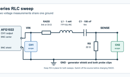
Move a 0.47 Ω current-sense resistor from the supply lead to the return lead. The resistor stays in series with the same load, so the current and its voltage drop should stay close to their previous values. The load’s return terminal changes voltage. Measure all three effects with a handheld meter, then use the INA180 amplifier output to estimate how strongly it amplifies the shunt voltage.
What the amplifier senses
A shunt is a resistor placed in the path of a current you want to measure. At its terminals, the voltage drop equals current times resistance. The INA180A1 amplifies the difference between its positive and negative sense inputs by a nominal factor of 20. The average voltage on the two sense pins is their common-mode voltage. Moving the shunt changes this average from about 5 V to a few tens of millivolts while leaving the differential input close to its original value.
With the shunt on the high side, the load return connects directly to the supply negative. On the low side, the return current passes through the shunt before reaching supply negative. The load’s local return then sits above the supply negative by roughly the shunt drop. That difference matters when a separate signal crosses from the load to a circuit that uses the supply negative as its reference.
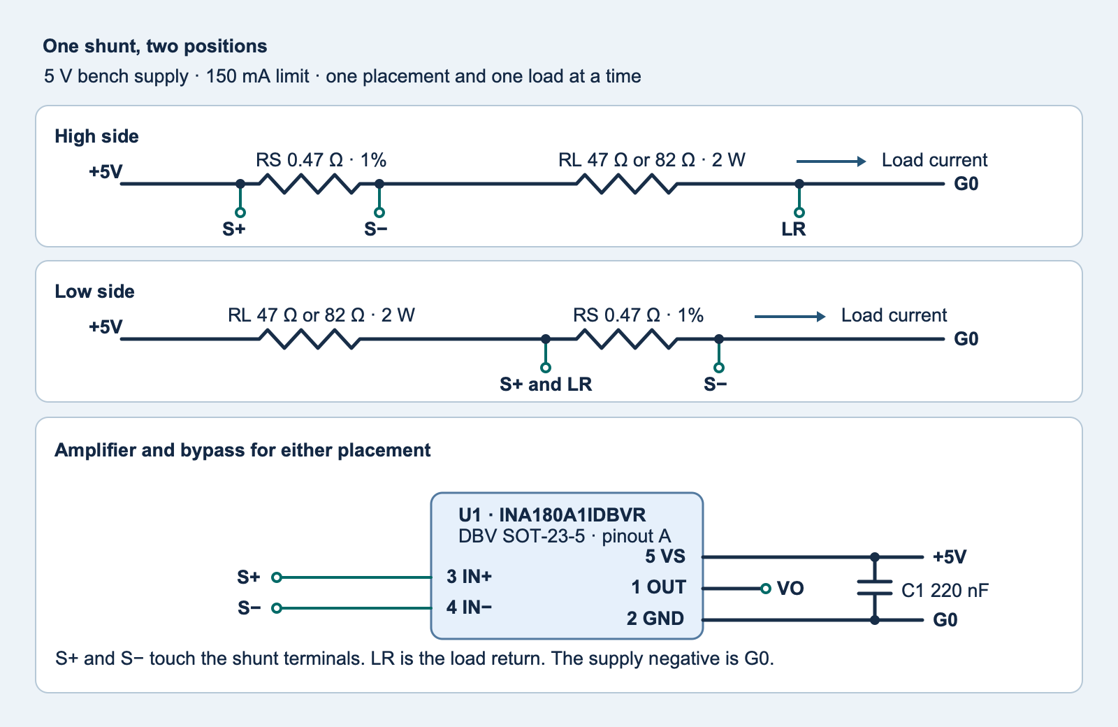
fixture.svg) · Full-size PNG.Parts and connections
- Use Texas Instruments INA180A1IDBVR in the five-lead DBV surface-mount SOT-23 package on a passive breakout. Find the pin-1 mark and confirm breakout-to-package continuity before wiring. The INA180A1 uses the manufacturer’s pinout A. Pin 1 is output VO, pin 2 is G0, pin 3 is IN+, pin 4 is IN−, and pin 5 is the supply VS. The INA180B family uses a different pin arrangement.
- Use a 0.47 Ω, 1%, 0.5 W shunt. Keep the same physical shunt throughout the exercise. Connect separate sense wires directly at the shunt terminations, inside the connections carrying load current. This Kelvin connection uses separate sense and current paths so wire and connector drops stay outside the sensed voltage. Keep the two sense leads short and similar in length. Connect a 220 nF, ±10%, 25 V or greater film capacitor directly across pins 5 and 2 to bypass supply noise.
- Prepare one 47 Ω and one 82 Ω load, each 1%, 2 W. Install one load at a time. Use a SIGLENT SPD3303X channel 1 in independent mode at 5.00 V with a 150 mA current limit, and leave the other channels disconnected. Designate channel 1 negative as G0. The amplifier and the load circuit share that one supply. Keep protective earth intact.
- On the high side, connect +5 V → S+ → shunt → S− → load → LR → G0. On the low side, connect +5 V → load → LR → S+ → shunt → S− → G0. Bring pin 2 and the supply capacitor return to G0 in both cases. Connect pin 3 to S+ and pin 4 to S− every time. Use VO only for the handheld voltmeter in this experiment.
The INA180 recommended supply range is 2.7–5.5 V. Its specified input common-mode range is −0.2 to +26 V relative to pin 2. This fixture uses one isolated 5 V supply for the entire circuit. It avoids negative shunt polarity and keeps the INA180 output well away from either rail while the load is connected. The datasheet gain-error row applies at output levels from 0.5 V to VS minus 0.5 V under its stated electrical-characteristic conditions. The analyzer uses that output window as a screening rule for this experiment.
Estimate the voltages before connecting the meter
For the series load circuit, I ≈ VS ÷ (RL + RS), VSH = I × RS, and VO ≈ 20 × VSH. These equations omit the amplifier’s input bias and output offset and the resistance of fixture wiring. VCM is the common-mode voltage, which you can estimate from S+ relative to G0 minus half of VSH. Across the high-side shunt the two pins are both close to 5 V. Across the low-side shunt they are both close to G0.
| Load | Current | Shunt drop | Ideal VO |
|---|---|---|---|
| 82 Ω | 60.63 mA | 28.50 mV | 0.570 V |
| 47 Ω | 105.33 mA | 49.50 mV | 0.990 V |
At 5.10 V with the 47 Ω load and both resistances at the low end of their 1% tolerances, current is about 109 mA and load power is about 0.55 W. The shunt dissipates about 6 mW at the heavy-load operating point. Use the stated resistor ratings, keep the load above the work surface, and let it cool before handling it. The 150 mA supply limit sits above the intended test current. Stop if the supply enters constant-current mode or the rail falls outside 4.90–5.10 V.
Record twelve sets of readings
Use a battery-operated Fluke 115 digital multimeter with the black lead in COM and the red lead in VΩ. Use its direct-current millivolt range for the shunt drop and LR. Use the 6 V direct-current range for the rail, S+ and VO, including the smaller low-side S+ reading. Using the specified ranges keeps the worksheet’s displayed-count error calculation consistent.
- With the supply off, wire the high-side circuit and fit the 82 Ω load. Verify pin numbers, pad polarity and the G0 return. Switch on. Let the readings settle before recording them. Leave the fixture disconnected from grounded scopes, USB instruments and other power sources throughout the exercise.
- Measure the rail at pin 5 relative to pin 2. With the battery meter floating, measure the shunt drop directly across S+ and S−, with red on S+. For the remaining readings place black on pin 2 and put red on S+, VO and LR in turn. Keep all other wiring in place. Enter volts for
rail_v,sense_plus_vandout_v, and millivolts forshunt_mvandload_return_mv. Measure S+ separately from the differential drop even when the shunt is on the low side. - Record three complete rounds with the same wiring and load, retaining each displayed reading. Turn off the supply and verify that the rail has fallen before changing the load. Repeat with 47 Ω. Turn off the supply again before moving the shunt and its Kelvin wires to the low side. Repeat three rounds per load in that placement.
- If VO is near the lower rail with either connected load, recheck the package, pin map, differential polarity and the connection from pin 5 to the supply. If LR on the low side is near G0 while the shunt still shows the expected drop, check where you put the LR probe and inspect for an unintended ground connection. A reading from an open-load test can help debug wiring, but this worksheet uses only the two loaded conditions.
Download the blank worksheet (ZIP: observations-blank.csv) or the experiment ZIP with the editable diagram, worksheet and code (ZIP: experiment-tests-v1.zip). Enter the measurements into a copy named observations.csv. The sheet fixes the topology, load and trial in each row. A value such as 0.990 belongs in out_v, while 49.5 belongs in shunt_mv. Use the default 0.470 Ω assumption or pass a measured four-wire value within the resistor’s 1% band. An ordinary two-wire ohms reading at this resistance includes the test leads.
Estimate gain from the change between two loads
For each placement, the analyzer takes the median of three readings at each load and estimates gain as (VO,47 − VO,82) ÷ (VSH,47 − VSH,82). A constant output offset cancels in the subtraction. An offset that changes with common-mode voltage, supply, or temperature can still affect the slope. The analyzer also reports the spread of the repeated readings, estimated current from the shunt drop, and how much higher LR is with the low-side shunt.
The Fluke 115 specifies DC accuracy of ±(0.5% of the reading + 2 counts). One count is 0.1 mV in the 600 mV range and 1 mV in the 6 V range. The program adds the specified errors at both endpoints for each difference. It divides the smallest possible output change by the largest possible shunt change for the lower gain bound and reverses that pairing for the upper bound. This meter-only interval excludes wiring drift, resistor heating and common-mode changes. Use it to decide whether your readings can distinguish the two estimated gains. With nominal voltages, the interval is about 18.7–21.4 V/V, wide enough that the setup cannot resolve a one-percent gain difference from those readings alone.
Run python3 shunt_compare.py observations.csv on a computer. The program reports inconsistent placement, missing rows and unresolved gain as worksheet errors. The provided tests exercise the complete analyzer with synthetic readings. Record bench measurements in the worksheet after running the fixture.
Complete Python worksheet analyzer
#!/usr/bin/env python3
"""Analyze the INA180 high-side/low-side voltage worksheet on a computer."""

import argparse
import csv
import json
import math
from pathlib import Path
from statistics import median
import sys


FIELDS = ("placement", "load_ohm", "trial", "rail_v", "sense_plus_v",
          "shunt_mv", "out_v", "load_return_mv")
PLACEMENTS = ("high", "low")
LOADS = ("82", "47")
TRIALS = ("1", "2", "3")
EXPECTED_KEYS = {
    (placement, load, trial)
    for placement in PLACEMENTS for load in LOADS for trial in TRIALS
}
# Worksheet plausibility ranges, wider than nominal fixture calculations.
SHUNT_WINDOWS_MV = {"82": (20, 36), "47": (40, 60)}


def require_range(name, value, minimum, maximum):
    try:
        number = float(value)
    except (TypeError, ValueError):
        raise ValueError(f"{name}: enter a number") from None
    if not math.isfinite(number) or not minimum <= number <= maximum:
        raise ValueError(f"{name}: expected {minimum:g} to {maximum:g}")
    return number


def read_trial(key, values):
    placement, load, _ = key
    rail = require_range("rail_v", values[0], 4.90, 5.10)
    sense_plus = require_range("sense_plus_v", values[1], -0.005, 5.15)
    shunt_mv = require_range("shunt_mv", values[2], *SHUNT_WINDOWS_MV[load])
    output = require_range("out_v", values[3], 0.50, rail - 0.50)
    lift_mv = require_range("load_return_mv", values[4], -5, 70)
    shunt = shunt_mv / 1000
    if placement == "high":
        if abs(sense_plus - rail) > 0.10 + 1e-12 or abs(lift_mv) > 5:
            raise ValueError("high-side sense pad should be near the rail and return near G0")
    elif abs(sense_plus - shunt) > 0.005 + 1e-12 or abs(lift_mv - shunt_mv) > 5 + 1e-12:
        raise ValueError("low-side sense pad and load return should follow the shunt drop")
    return {
        "rail_v": rail,
        "shunt_mv": shunt_mv,
        "out_v": output,
        "load_return_mv": lift_mv,
        "common_mode_v": sense_plus - shunt / 2,
    }


def read_worksheet(stream):
    lines = csv.reader(stream, strict=True)
    if tuple(next(lines, ())) != FIELDS:
        raise ValueError("use the exact worksheet headings")
    trials = {}
    for line_number, row in enumerate(lines, start=2):
        key = tuple(row[:3])
        if len(row) != len(FIELDS) or key not in EXPECTED_KEYS:
            raise ValueError(f"line {line_number}: invalid placement, load, trial or column count")
        if key in trials:
            raise ValueError(f"line {line_number}: repeated trial {key}")
        try:
            trials[key] = read_trial(key, row[3:])
        except ValueError as error:
            raise ValueError(f"line {line_number}: {error}") from error
    if trials.keys() != EXPECTED_KEYS:
        raise ValueError("need all twelve trials")
    rails = [trial["rail_v"] for trial in trials.values()]
    if max(rails) - min(rails) > 0.10 + 1e-12:
        raise ValueError("fixture rail changed by more than 0.10 V")
    return trials


def summarize(trials, shunt_ohms):
    group = {
        name: median(row[name] for row in trials)
        for name in trials[0]
    }
    group["estimated_current_ma"] = group["shunt_mv"] / shunt_ohms
    for name in ("shunt_mv", "out_v"):
        values = [row[name] for row in trials]
        group[name + "_spread"] = max(values) - min(values)
    return group


def meter_delta_uncertainty(smaller, larger, count_v):
    # Fluke 115 DC accuracy is 0.5% of each reading plus two display counts.
    return 0.005 * (abs(smaller) + abs(larger)) + 4 * count_v


def gain_summary(light, heavy):
    x_low = light["shunt_mv"] / 1000
    x_high = heavy["shunt_mv"] / 1000
    y_low = light["out_v"]
    y_high = heavy["out_v"]
    delta_x = x_high - x_low
    delta_y = y_high - y_low
    error_x = meter_delta_uncertainty(x_low, x_high, 0.0001)
    error_y = meter_delta_uncertainty(y_low, y_high, 0.001)
    if delta_y <= error_y or delta_x <= error_x:
        raise ValueError("load change did not resolve a positive output and shunt change")
    return {
        "measured_v_per_v": delta_y / delta_x,
        "meter_only_interval_v_per_v": [
            (delta_y - error_y) / (delta_x + error_x),
            (delta_y + error_y) / (delta_x - error_x),
        ],
        "shunt_change_mv": delta_x * 1000,
        "out_change_v": delta_y,
    }


def analyze(stream, shunt_ohms):
    shunt_ohms = require_range("shunt_ohms", shunt_ohms, 0.4653, 0.4747)
    trials = read_worksheet(stream)
    by_placement = {}
    for placement in PLACEMENTS:
        loads = {
            load: summarize([trials[placement, load, trial] for trial in TRIALS], shunt_ohms)
            for load in LOADS
        }
        by_placement[placement] = {
            "loads_ohm": loads,
            "two_point_gain": gain_summary(loads["82"], loads["47"]),
        }
    return {
        "assumed_shunt_ohms": shunt_ohms,
        "placement": by_placement,
        "low_minus_high_return_mv": {
            load: by_placement["low"]["loads_ohm"][load]["load_return_mv"]
            - by_placement["high"]["loads_ohm"][load]["load_return_mv"]
            for load in LOADS
        },
    }


def main():
    parser = argparse.ArgumentParser(description=__doc__)
    parser.add_argument("worksheet", type=Path)
    parser.add_argument("--shunt-ohms", type=float, default=0.470)
    args = parser.parse_args()
    try:
        with args.worksheet.open(newline="", encoding="utf-8-sig") as stream:
            result = analyze(stream, args.shunt_ohms)
    except (OSError, ValueError, csv.Error) as error:
        print(f"Worksheet error: {error}", file=sys.stderr)
        return 2
    print(json.dumps(result, indent=2, allow_nan=False))
    return 0


if __name__ == "__main__":
    sys.exit(main())
The digital INA219 calibration and conversion experiment follows the raw shunt voltage through a different measurement chain.
Challenge. Where does the load return sit?
Both placements show a 50 mV shunt drop and about 1 V at VO. Which load return can you connect directly to a separate circuit’s G0 without bypassing the shunt?
The high-side load return already joins G0. The low-side return is about 50 mV above G0. A low-resistance connection between that return and G0 gives the load current a parallel path, reducing the current through the shunt and corrupting the reading.
Primary references
- Texas Instruments INA180 data sheet, SBOS741H, sections 6, 7.3, 7.5, 8.3.2, 9.1.1 and 9.4.1. INA180A1IDBVR orderable part.
- Fluke 115 DC accuracy and ranges. Fluke user manual.
- SIGLENT SPD3303X isolated outputs. SIGLENT current-limit operation.
Download the complete reader files (ZIP) for the original editable drawing, PNG, worksheet and code in ina180-shunt-placement-ground-lift. The full main program is also included above.