A value arriving over a wire is not automatically trustworthy. It may be cut in half, damaged or never arrive at all. This project sends a knob reading between two Pico boards and adds three small but useful ideas: a recognizable frame, an error-detecting checksum and a freshness timeout.
The electrical link
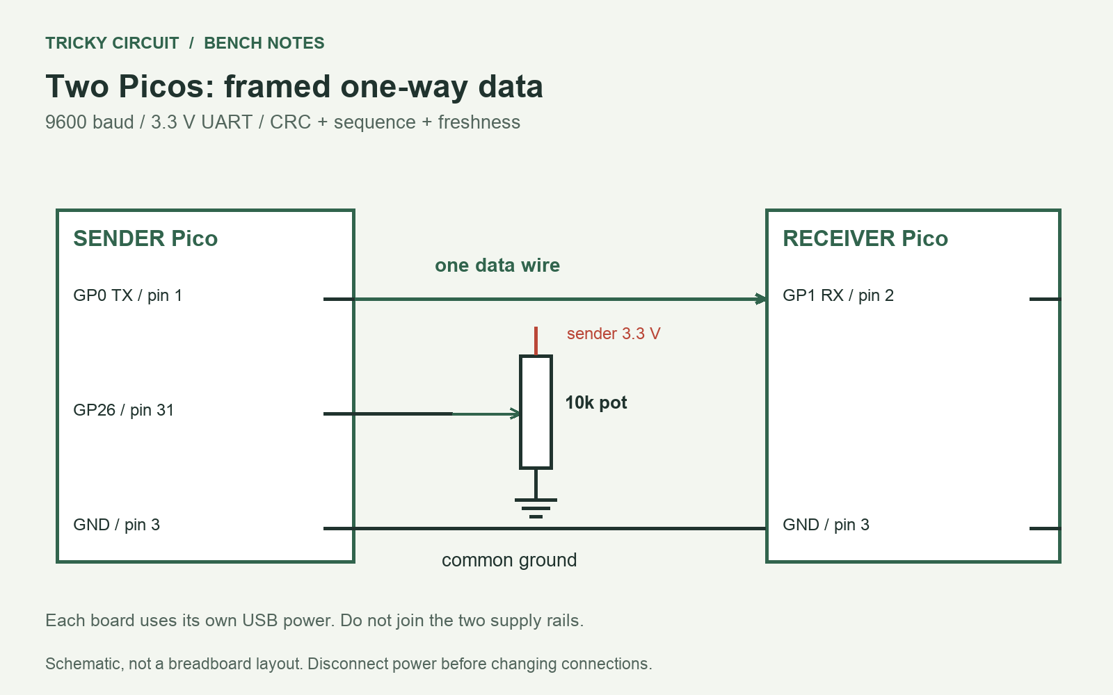
UART means universal asynchronous receiver/transmitter. It sends bits according to an agreed speed and framing without a separate clock wire. Here both boards use 9600 baud with the default eight data bits, no parity and one stop bit. TX means transmit and RX means receive. Connect the sender’s TX to the receiver’s RX and join their grounds.
The boards have 3.3 V logic. This is not an RS-232 interface, whose voltage levels differ. Keep the bench wires short and do not connect the supply rails of two separately USB-powered boards. USB means Universal Serial Bus; here it powers each board and supplies its programming console.
Parts to gather
- Two original Raspberry Pi Pico boards, each with MicroPython 1.26
- One 10 kΩ potentiometer for the sender
- Two short signal/ground jumpers and separate USB power connections
Complete connections
| Connection | Purpose |
|---|---|
| Sender GP0 TX, physical pin 1 → receiver GP1 RX, physical pin 2 | One-way 3.3 V data. Do not connect two transmit outputs together. |
| Sender GND, pin 3 → receiver GND, pin 3 | Common signal reference; do not link the two 5 V or 3.3 V supply rails. |
| Sender 3V3 pin 36 → potentiometer outer terminal; other outer terminal → GND | Potentiometer wiper → sender GP26, physical pin 31. |
| Receiver GP0 and sender GP1 left unconnected | The program creates a UART peripheral but uses only one direction. |
What is inside a message?
The sender formats a sequence number and a raw knob reading, then appends an asterisk, four hexadecimal checksum characters and a newline. CRC means cyclic redundancy check, an error-detecting calculation over the transmitted bytes. This example uses CRC-16 with polynomial 0x1021, starting value 0xFFFF, no reflected bits and no final XOR. The standard test input 123456789 gives 0x29B1 for this variant.
The receiver waits for a newline before decoding. It rejects a bad checksum, malformed field or out-of-range number. A frame longer than 40 bytes is discarded up to its newline so that unbounded input cannot grow the buffer forever. The sequence number wraps from 65,535 to zero; a discontinuity is reported as a gap or restart, not silently described as normal delivery.
Complete MicroPython program for both boards
"""Two Picos: sender GP0 -> receiver GP1, common GND, separate USB power.
Both use MicroPython 1.26. Set ROLE on each board. No 5V/3V3 rail link.
"""
ROLE = "sender"  # change to "receiver" on the other board

def crc16(data):
    crc = 0xFFFF
    for byte in data:
        crc ^= byte << 8
        for _ in range(8):
            crc = ((crc << 1) ^ 0x1021) & 0xFFFF if crc & 0x8000 else (crc << 1) & 0xFFFF
    return crc

def encode(sequence, raw):
    body = ("%d,%d" % (sequence, raw)).encode()
    return body + ("*%04X\n" % crc16(body)).encode()

def decode(line):
    body, check = line.strip().split(b"*")
    if len(check) != 4 or crc16(body) != int(check, 16):
        raise ValueError("Bad checksum")
    seq_text, raw_text = body.split(b",")
    seq, raw = int(seq_text), int(raw_text)
    if not 0 <= seq <= 65535 or not 0 <= raw <= 65535:
        raise ValueError("Field out of range")
    return seq, raw

def main():
    from machine import UART, Pin, ADC
    from time import ticks_ms, ticks_diff, sleep_ms
    uart = UART(0, baudrate=9600, tx=Pin(0), rx=Pin(1), timeout=0)
    if ROLE == "sender":
        adc = ADC(Pin(26)); seq = 0
        while True:
            uart.write(encode(seq, adc.read_u16()))
            seq = (seq + 1) & 0xFFFF
            sleep_ms(1000)
    elif ROLE == "receiver":
        buffer = bytearray(); discard = False
        last_good = None; last_seq = None; reported = None
        while True:
            incoming = uart.read(64) or b""
            for byte in incoming:
                if byte == 10:
                    if not discard:
                        try:
                            seq, raw = decode(bytes(buffer))
                            if last_seq is not None and seq != (last_seq + 1) & 0xFFFF:
                                print("SEQUENCE_GAP_OR_RESTART", last_seq, seq)
                            last_seq = seq; last_good = ticks_ms()
                            print("SAMPLE", seq, raw)
                        except (ValueError, TypeError):
                            print("REJECTED_FRAME")
                    buffer = bytearray(); discard = False
                elif not discard:
                    if len(buffer) >= 40:
                        buffer = bytearray(); discard = True
                    else:
                        buffer.append(byte)
            state = "WAITING" if last_good is None else ("STALE" if ticks_diff(ticks_ms(), last_good) > 3500 else "FRESH")
            if state != reported:
                print(state); reported = state
            sleep_ms(10)
    else:
        raise ValueError("ROLE must be sender or receiver")

if __name__ == "__main__":
    main()
Load, connect and exercise
- With power disconnected, wire the common ground, data line and sender potentiometer according to the diagram.
- Save the program as main.py on both boards. Use ROLE = “sender” on one and ROLE = “receiver” on the other.
- Open the receiver’s console. It should report WAITING until the first valid message, then FRESH and numbered samples approximately once a second.
- Turn the potentiometer. The raw value should change without changing the message format.
- Unplug the data jumper while leaving both boards powered. After 3.5 seconds without a good frame, expect STALE.
- Reconnect the jumper. A partial first line may be rejected; a following complete valid frame should restore FRESH.
Understand what the checks do
The checksum detects many accidental transmission errors; it is not encryption, authentication or a guarantee that every possible corruption is detected. Anyone controlling the sender can calculate a matching checksum for invented data. Similarly, a duplicate valid frame can update the arrival time while the sequence warning reveals repetition. The timeout measures recent receipt, not the physical freshness of an independently sampled remote sensor.
The potentiometer measurement is deliberately simple so you can focus on communication. A future real sensor node should include measurement time, units and error status. A sensor failure must not be replaced with a plausible zero just to keep the packet numeric.
Fault tests in software
The accompanying checks validate the CRC reference vector, round-trip frames, damaged payloads, negative and oversized fields. For a bench corruption experiment, change one digit in an encoded test line without updating its checksum. The decoder should reject it. If nothing arrives, verify TX-to-RX rather than TX-to-TX, common ground, the selected ROLE and matching baud settings.
Challenge: why use a newline if every message has a checksum?
The receiver needs to know which bytes belong to one candidate message before it can calculate that message’s checksum. A delimiter supplies the boundary; the checksum then checks the bounded content.
Sources and related learning
Explore the Tricky Circuit interactive lessons. This article presents a design and software checks; no physical build results are claimed.