1️⃣ Concept Overview
- Dual NE555 Setup:
- NE555 #1 (LFO): Generates a slow oscillating (modulation) signal. This low-frequency signal will modulate the timing components (resistor or capacitor) of the second timer.
- NE555 #2 (Audio Oscillator): Operates in astable mode to generate a square wave that drives a speaker. Its frequency is modulated by the LFO, creating a sweeping siren effect.
- How It Works:
- The LFO (first 555) produces a slowly varying voltage.
- This voltage is used to vary one of the resistors or control inputs in the audio oscillator (second 555), thus altering its output frequency over time.
2️⃣ Components Needed
- 2 × NE555 Timer ICs
- Resistors:
- Fixed resistors for setting baseline timing (e.g., R1, R3)
- A resistor (or potentiometer) for modulation (e.g., R2) that may be partly replaced or influenced by the LFO output
- Capacitors:
- Timing capacitor(s) for each NE555 circuit
- Diodes (optional):
- For directing current in the modulation network, if needed
- Speaker or Piezo Buzzer:
- To output the audible siren sound
- Breadboard & Jumper Wires
- Power Supply:
- Typically 5V DC
3️⃣ Circuit Design & Schematic Explanation
A. NE555 #1: The Low-Frequency Oscillator (LFO)
- Purpose: Generate a slow, oscillating voltage (e.g., 0.5–2 Hz).
- Configuration: Set up in astable mode with large resistor and capacitor values to produce a low frequency.
- Output: The output at pin 3 will be a square wave that oscillates between near 0V and VCC.
B. NE555 #2: The Audio Oscillator
- Purpose: Produce the primary audible tone.
- Configuration: Also in astable mode, but with timing components chosen for audio frequencies (typically a few hundred Hertz to a couple of kHz).
- Frequency Modulation:
- The modulation from NE555 #1 is used to vary one of the timing resistors or an equivalent control parameter in the audio oscillator circuit.
- One common approach is to use a transistor or a diode network so that the LFO output effectively “adds” or “subtracts” resistance in the RC network of the second timer, causing its frequency to sweep.
C. Conceptual Schematic
Note:
- The modulation circuit can be as simple as connecting the LFO output through a resistor or diode network to the timing resistor (R2) of the audio oscillator.
- You might use a potentiometer in parallel to fine-tune the modulation effect.
- Coupling components (such as capacitors) might be needed to block DC and ensure the proper biasing of each stage.
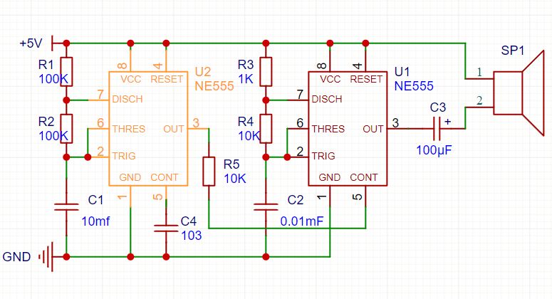
4️⃣ Example Component Values (For Reference Only)
- LFO (Timer #1):
- R1 = 100 kΩ
- R2 = 100 kΩ (or a potentiometer for adjustable modulation)
- C1 = 10 µF
- Result: Frequency roughly around 1 Hz (adjust values as needed)
- Audio Oscillator (Timer #2):
- R3 = 1 kΩ
- R4 = 10 kΩ (or the resistor that will be modulated)
- C2 = 0.01 µF
- Result: Base frequency in the audible range (e.g., 500 Hz to 2 kHz, subject to modulation)
Reminder: These values are approximate. You may need to experiment with resistor and capacitor values to achieve the desired siren effect.
5️⃣ Final Tips
- Experimentation:
- Tweak resistor and capacitor values in both circuits to get a smooth frequency sweep.
- Modulation Circuit:
- Consider using a small transistor amplifier or a diode network if a direct connection doesn’t provide the desired modulation.
- Sound Amplification:
- If the speaker’s output is too low, add a simple transistor amplifier stage between the audio oscillator’s output and the speaker.
- Prototyping:
- Build and test each NE555 circuit separately on a breadboard before combining them.
🎯 Conclusion
Using two NE555 timers—one for generating a low-frequency modulation signal and the other for producing an audible tone—you can create a siren circuit with a sweeping frequency effect. This project is an excellent way to explore the versatility of the NE555 and the principles of frequency modulation.