The KY-023 Joystick Module is an analog joystick similar to those used in gaming controllers. It has two potentiometers (X & Y axes) and a push-button switch. This module is commonly used with Arduino, Raspberry Pi, and other microcontrollers for motion control, robotics, and gaming applications.
🔹 1. KY-023 Joystick Module Pinout
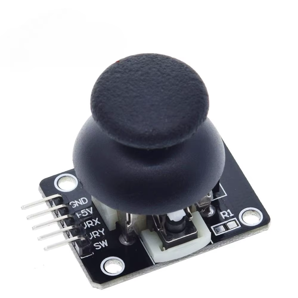
The KY-023 module has 5 pins:
| Pin | Label | Function |
|---|---|---|
| VCC | Power | Connects to 5V (or 3.3V) |
| GND | Ground | Common ground for the circuit |
| VRX | X-Axis | Outputs an analog signal (0-1023 on Arduino) |
| VRY | Y-Axis | Outputs an analog signal (0-1023 on Arduino) |
| SW | Switch | Outputs LOW (0V) when pressed, HIGH (5V) when released |
📌 Note:
- VRX and VRY are analog outputs and should be connected to analog input pins (A0, A1, etc.) on an Arduino.
- SW is a digital output and can be connected to any digital input pin.
🔹 2. How the KY-023 Joystick Works
✅ X & Y Axis (Analog Output)
- Inside the joystick are two potentiometers, one for each axis.
- Moving the joystick left/right or up/down changes the resistance, generating an analog voltage.
| Position | VRX Value | VRY Value |
|---|---|---|
| Center | ~512 | ~512 |
| Left | 0 | ~512 |
| Right | 1023 | ~512 |
| Up | ~512 | 0 |
| Down | ~512 | 1023 |
✅ Push Button (Digital Output)
- Pressing the joystick closes the switch (
SWpin). - It reads LOW (0V) when pressed and HIGH (5V) when released.
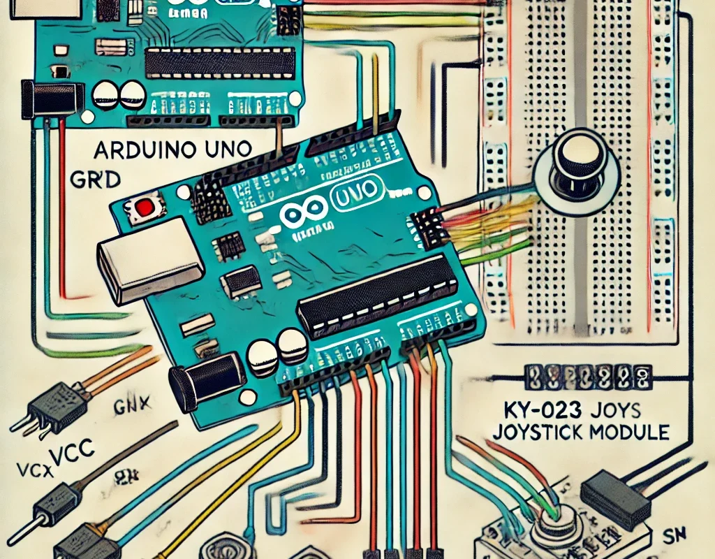
🔹 3. Connecting KY-023 to Arduino
🛠 Required Components
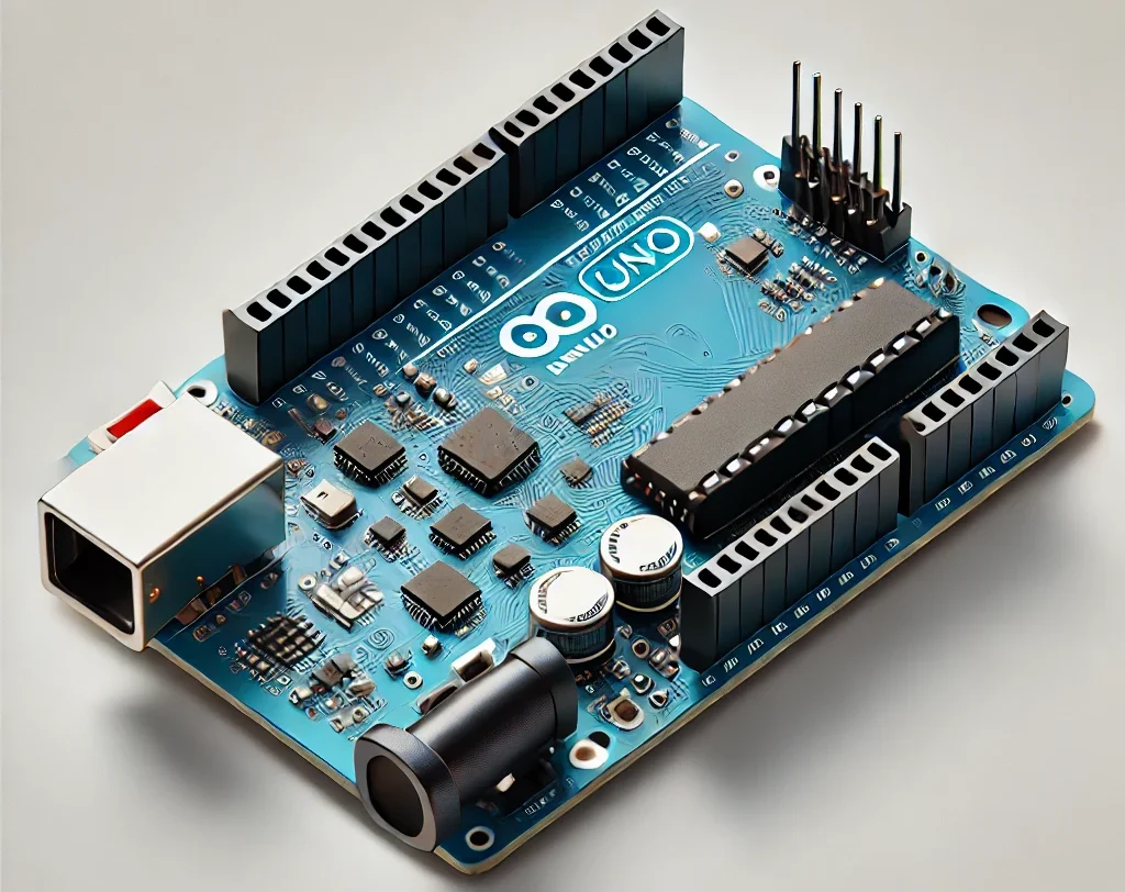
- 1x Arduino Board (Uno, Mega, Nano, etc.)
- 1x KY-023 Joystick Module
- Jumper Wires
🛠 Wiring Diagram
| KY-023 Pin | Arduino Pin |
|---|---|
| VCC | 5V |
| GND | GND |
| VRX | A0 |
| VRY | A1 |
| SW | D2 |
🔹 4. Arduino Code to Read Joystick Values
This code reads X & Y axis values and detects button presses, displaying the data in the Serial Monitor.
#define VRX_PIN A0  // X-axis
#define VRY_PIN A1  // Y-axis
#define SW_PIN 2    // Switch button

void setup() {
    Serial.begin(9600);  // Start Serial Monitor
    pinMode(SW_PIN, INPUT_PULLUP); // Enable internal pull-up resistor
}

void loop() {
    int xValue = analogRead(VRX_PIN);  // Read X-axis
    int yValue = analogRead(VRY_PIN);  // Read Y-axis
    int buttonState = digitalRead(SW_PIN); // Read button state

    Serial.print("X: "); Serial.print(xValue);
    Serial.print(" | Y: "); Serial.print(yValue);
    Serial.print(" | Button: "); Serial.println(buttonState == LOW ? "Pressed" : "Released");

    delay(100);  // Small delay to avoid spamming Serial Monitor
}
📌 Explanation:
- Reads VRX and VRY as analog values (0-1023).
- Reads SW as a digital input (LOW when pressed).
- Displays values in Serial Monitor.
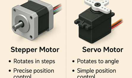
🔹 5. Using KY-023 for a Simple Game Controller
You can use the joystick to control a servo, LED, or even a robot.
Example: Move a Servo with Joystick
#include <Servo.h>

Servo myServo;
#define VRX_PIN A0  // X-axis for servo control

void setup() {
    myServo.attach(9);  // Servo on pin 9
}

void loop() {
    int xValue = analogRead(VRX_PIN); // Read joystick X-axis
    int servoAngle = map(xValue, 0, 1023, 0, 180); // Convert to servo angle
    myServo.write(servoAngle); // Move servo
    delay(10);
}
🔹 6. Applications of KY-023 Joystick
✅ Robotics – Control robots using hand gestures.
✅ Game Controllers – DIY joystick for games.
✅ Camera Pan/Tilt Control – Move servos for a camera gimbal.
✅ Remote Control Vehicles – Control motors and direction.
🔹 7. Troubleshooting Tips
- If values jump randomly, check loose connections.
- If the button doesn’t work, try using INPUT_PULLUP in
pinMode(SW_PIN, INPUT_PULLUP);. - If X or Y values are stuck, check if the joystick springs back to center.
🎯 Conclusion
The KY-023 joystick module is a versatile input device that works with Arduino, Raspberry Pi, and other microcontrollers. It provides analog motion control and a built-in button, making it perfect for robotics, games, and interactive projects.