A photodiode sees both your light-emitting diode (LED) and the room. If the room gets brighter, the voltage can rise even though your LED has stayed the same. Pulse the LED and measure the detector just before, during and just after each flash. The two off intervals give you a local estimate of the background to subtract.
Build the light source and the detector
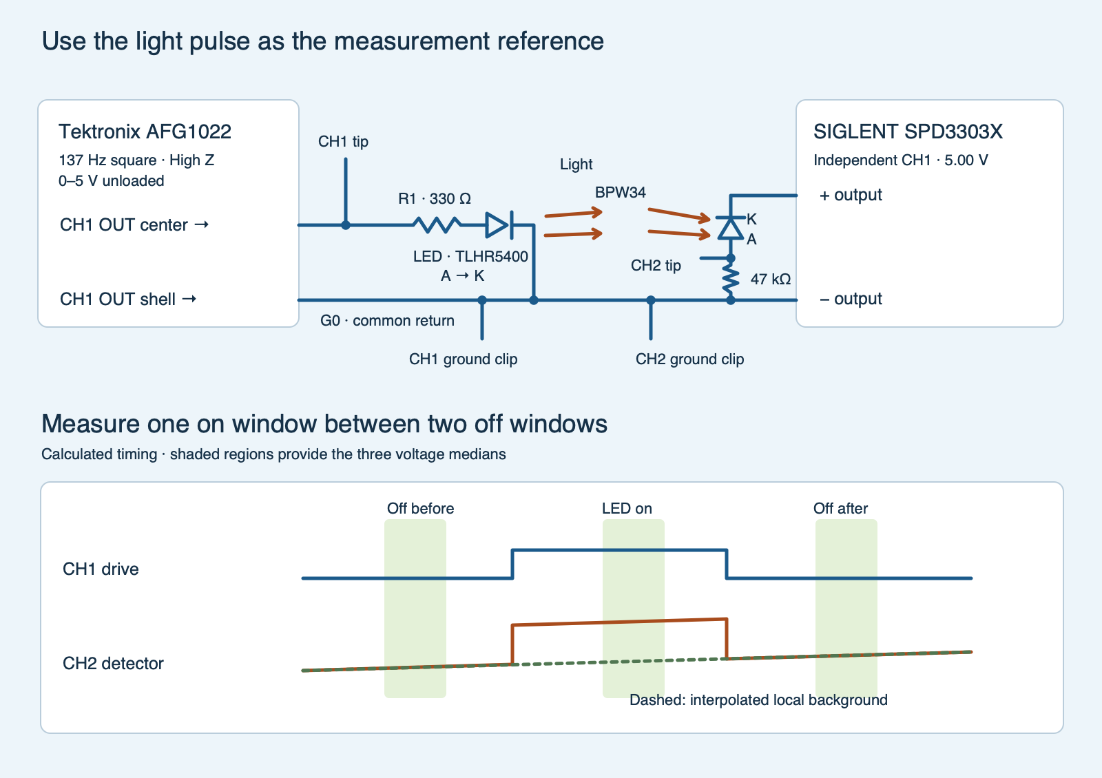
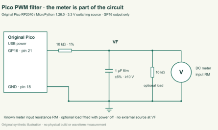
paired-light.svg)- Emitter. With the outputs off, connect a Tektronix AFG1022 channel 1 BNC output center to a 330 Ω resistor and then to the anode of a Vishay TLHR5400 red LED. Connect its cathode to the generator shell at circuit ground, G0. Follow the Vishay package drawing, or confirm polarity with the diode mode on an unpowered loose part. Use a Vishay MRS25000C3300FCT00, 330 Ω ±1% axial resistor. Set the generator to a 137 Hz square wave, 5.0 V peak to peak, 2.50 V offset, High Z display load. This gives nominal unloaded levels of 0 to 5 V at 50% duty. The generator still has nominal 50 Ω output resistance, so its driven high will fall slightly under load.
- Detector. Use the leaded Vishay BPW34 silicon PIN photodiode. Its intrinsic semiconductor layer helps collect charge when light reaches the device. Connect its marked cathode to +5.00 V on an independent SIGLENT SPD3303X channel 1. Return that channel’s negative terminal to G0. Connect the photodiode anode to node SENSE and from SENSE through a Vishay MRS25000C4702FCT00 47 kΩ ±1% resistor to G0. Use the datasheet drawing to find the BPW34 cathode mark. Keep the detector reverse-biased; the supply holds the cathode above the anode. Set a 20 mA bench-supply current limit and use the supply in constant-voltage mode.
- Probes. Use a RIGOL DHO804 with two PVP2350 probes set to 10× on both the probes and the scope. Connect the channel 1 tip to the generator output before the 330 Ω resistor and the channel 2 tip to SENSE. Both ground clips go to G0 only. Keep protective earth intact and use this wiring only with the stated low-voltage supplies. Choose DC input coupling for both channels so the background voltage remains visible.
The TLHR5400 datasheet lists about 2 V forward drop under its stated 20 mA test condition. Using 2 V only as a rough estimate here gives (5 − 2)/(330 + 50) ≈ 7.9 mA at the pulse top. Even a 5.5 V source with zero assumed LED drop and a 330 Ω resistor at its −1% tolerance would give about 16.8 mA and 0.093 W in the resistor. At room temperature this is below the datasheet’s 30 mA DC limit for the LED and the resistor’s 0.6 W rating at 70 °C. The BPW34 uses 5 V of reverse bias in one of Vishay’s test conditions and has a 60 V absolute maximum reverse rating. The experiment uses the observed drive plateau as timing and a consistency check, while actual LED current also depends on the forward drop. The probe presents about 10 MΩ at direct current, so the detector gain for settled windows is approximately 47 kΩ ∥ 10 MΩ = 46.78 kΩ. A 0.170 V difference represents about 3.63 µA of additional current. A SENSE value of 4.50 V on the 5 V supply leaves only about 0.50 V of reverse bias, so the checker screens measurements above 4.50 V.
Change the background without moving the LED or detector
Fix the LED and photodiode facing each other on an insulating fixture with a small gap, initially around 20 mm. A short, opaque cap that fits over the LED will later block its light without moving either part or shading the photodiode from the side. Place an adjustable battery-powered lamp off-axis to change the detector’s background light. Keep the lamp on a stable output setting during each capture. If it produces optical flicker, change the light source. Keep all four conditions in the same location after the fixture has settled.
| Mode | Background light | Pulsed LED |
|---|---|---|
dim |
Lower light | Uncovered |
bright |
Higher light | Uncovered |
blocked |
Same as bright | Cap fitted |
restored |
Same as bright | Cap removed |
Trigger the scope on the rising channel 1 edge near 2.5 V. Capture both channels together with a time span of about 80 ms. Verify a sample interval no larger than 50 µs and choose vertical settings that show the entire detector trace without clipping. Use the same ranges and probe settings across the four records. On the DHO804 use Storage → Save → Choose → Save Wave and the Memory source with comma-separated values (CSV). A 10 kpts memory depth should let the exported records fit the script’s total limit of 100,000 rows, but verify the actual interval and length. Leave the generator on for all four records, including when the cap is fitted. Record the physical conditions in the blank worksheet (ZIP: observations-blank.csv).
Before collecting the final records, check that SENSE stays below 4.50 V in the brighter trial and changes visibly when the uncovered LED turns on. If the ambient level is too high, reduce it. If the recovered pulse is too small, adjust the distance or shield stray light, then start the four-record sequence again. A change to the drive, circuit or probe geometry can also change the measurement.
Estimate the light that follows the LED
At 137 Hz, a full period is about 7.30 ms and each nominal on or off interval lasts 3.65 ms. The analysis uses only the middle 35–65% of each interval for the three voltage medians so switching edges can settle. The drive trace sets the window times. For each LED-on window the script finds a preceding off median B0 at t0, a following off median B1 at t1, and an on median Von at t. Linear interpolation gives the estimated background at the on time:
B(t) = B0 + (B1 − B0)(t − t0)/(t1 − t0). The recovered voltage is ΔV = Von − B(t).
A steady background adds equally to the three medians and cancels. A background that varies linearly across a single pulse is also removed by interpolation. Choosing 137 Hz avoids matching common 100 Hz or 120 Hz lighting flicker exactly, but fast or periodic environmental changes can still affect the result. This method is a simple form of synchronous detection, which uses a known timing signal to distinguish the part of the measurement that follows it. Here it is a voltage difference, not a calibrated light level.
Run the comparison and keep the controls
In each Memory export use the common time column, CH1 drive and CH2 detector voltage. Preserve row order and simultaneous values. Remove instrument header lines, convert time to seconds and both channels to volts if needed, and prepend the trial name to each data row. Combine the four records into one CSV with the single header mode,time_s,drive_v,sense_v. Run python3 paired_light.py capture.csv --sense-ohm 47000, replacing 47000 with the unpowered measurement of the sense resistor when available. Without that argument it uses 47 kΩ nominal. The checker requires at least four complete bracketed pulses per record, confirms the driven high/low plateaus and pulse timing, and rejects excessive variation or detector voltage outside its fixture limits.
The brighter condition must add at least 0.100 V to the background, while the three unblocked records recover comparable positive LED signals. The blocked and restored records must preserve the brighter background within 0.070 V. The blocked record must reduce the recovered signal to a small residual even though the measured drive remains similar. This control helps distinguish actual optical pickup from a repeatable disturbance that follows the generator electrically. The acceptance thresholds are choices for this setup, and the comparison does not detect every kind of interference.
Exit 0 means the four exported records support the comparison. Exit 1 means the inputs or controls are unresolved. Exit 2 reports a file or parsing error. If the shielded LED still produces a recovered signal, check for light leaks and coupling through the wiring or ground. If the off readings wander appreciably between windows, use a steadier background and capture again. The included sample and host tests are synthetic. The article contains no physical bench results.
Predict what a drifting background would do
Suppose the off medians are 0.80 V before the pulse and 0.86 V after it. The on window is midway between them and measures 1.00 V. What is the corrected response?
Answer
The interpolated off level is 0.83 V and the response is 0.17 V, about 3.63 µA with a 46.78 kΩ effective load. Using only the first off value would overestimate the response by 0.03 V. This arithmetic case illustrates the correction. The packaged checker would flag that 0.06 V off-to-off change under its 0.05 V fixture limit.
Full Python analyzer
Download the standalone analyzer (ZIP: paired_light.py) or use the experiment archive (ZIP: experiment-tests-v1.zip) for the SVG, worksheet, calculated example and tests.
Complete source for paired_light.py
#!/usr/bin/env python3
"""Estimate pulsed light above ambient using bracketed dark windows per cycle."""

import argparse
from bisect import bisect_left, bisect_right
import csv
import math
from pathlib import Path
from statistics import median
import sys


MODES = ("dim", "bright", "blocked", "restored")
HEADER = ("mode", "time_s", "drive_v", "sense_v")
PERIOD = 1 / 137
ROUNDOFF = 1e-12


class EvidenceError(ValueError):
    """The observations do not establish the intended comparison."""


def require(ok, location, message):
    if not ok:
        raise EvidenceError(f"{location}: {message}")


def load(path):
    cases = {name: [] for name in MODES}
    with Path(path).open(newline="", encoding="utf-8-sig") as stream:
        reader = csv.reader(stream, strict=True)
        require(tuple(next(reader, [])) == HEADER, "CSV", "use mode,time_s,drive_v,sense_v")
        for i, row in enumerate(reader, 2):
            label = f"line {i}"
            require(i <= 100_001 and len(row) == 4 and row[0] in cases,
                    label, "unexpected field, mode or row limit")
            try:
                samples = tuple(float(value) for value in row[1:])
            except ValueError as error:
                raise EvidenceError(f"{label}: samples must be numbers") from error
            cases[row[0]].append(samples)
    return cases


def extract_edges(rows, label):
    require(bool(rows), label, "no samples")
    for time, drive, detector in rows:
        require(all(math.isfinite(x) for x in (time, drive, detector)), label, "non-finite sample")
        require(abs(time) <= 10 and -.3 <= drive <= 5.5, label, "scope time or drive outside bounds")
        require(-.05 <= detector <= 4.50, label, "detector headroom screen failed")
    edges = []
    for (t0, d0, _), (t1, d1, _) in zip(rows, rows[1:]):
        require(0 < t1 - t0 <= .00005 + ROUNDOFF,
                label, "sample time moved backward or a gap exceeds 50 microseconds")
        if (d0 >= 2.5) != (d1 >= 2.5):
            edge = t0 + (t1-t0) * (2.5-d0) / (d1-d0)
            edges.append((edge, d1 >= 2.5))
    return edges


def window(rows, times, begin, end, led_on, label):
    width = end - begin
    start = bisect_left(times, begin + .35 * width)
    stop = bisect_right(times, begin + .65 * width)
    points = rows[start:stop]
    require(len(points) >= 12, label, "too few in-window samples")
    ts, ds, vs = zip(*points)
    drive = median(ds)
    require((4.2 <= drive <= 5.2 if led_on else -.10 <= drive <= .20)
            and max(ds) - min(ds) <= .10 + ROUNDOFF, label, "drive plateaus are outside the fixture screen")
    require(max(vs) - min(vs) <= .060 + ROUNDOFF, label, "detector plateau spread is too large")
    return median(ts), median(vs), drive


def summarize(rows, label):
    edges = extract_edges(rows, label)
    times = [point[0] for point in rows]
    cycles = []
    for chunk, other, third, fourth in zip(edges, edges[1:], edges[2:], edges[3:]):
        if tuple(part[1] for part in (chunk, other, third, fourth)) != (False, True, False, True):
            continue
        previous_fall, rise, fall, next_rise = (part[0] for part in (chunk, other, third, fourth))
        period = next_rise - rise
        require(.975 * PERIOD - ROUNDOFF <= period <= 1.025 * PERIOD + ROUNDOFF
                and .975 * PERIOD - ROUNDOFF <= fall - previous_fall <= 1.025 * PERIOD + ROUNDOFF,
                label, "drive frequency differs from 137 Hz")
        require(.45 - ROUNDOFF <= (fall - rise) / period <= .55 + ROUNDOFF, label, "duty cycle differs from 50 percent")
        t0, low0, _ = window(rows, times, previous_fall, rise, False, label)
        tmid, peak, drive = window(rows, times, rise, fall, True, label)
        t1, low1, _ = window(rows, times, fall, next_rise, False, label)
        require(abs(low1-low0) <= .050 + ROUNDOFF, label, "background changed between dark windows")
        ambient = low0 + (low1-low0) * (tmid-t0) / (t1-t0)
        cycles.append((ambient, peak-ambient, drive))
    require(len(cycles) >= 4, label, "need four full bracketed LED pulses")
    background, delta, drive = zip(*cycles)
    require(max(delta) - min(delta) <= .050 + ROUNDOFF
            and max(background) - min(background) <= .070 + ROUNDOFF,
            label, "background or recovered amplitudes are not stable across cycles")
    return {"background_v": median(background), "delta_v": median(delta),
            "drive_v": median(drive), "cycles": len(cycles)}


def compare(cases, measured_ohm):
    require(math.isfinite(measured_ohm) and 45_000 <= measured_ohm <= 49_000,
            "fixture", "sense resistor must be near 47 kilohms")
    result = {name: summarize(cases[name], name) for name in MODES}
    dim, bright, blocked, restored = (result[name] for name in MODES)
    require(bright["background_v"] - dim["background_v"] >= .100 - ROUNDOFF,
            "comparison", "need at least 100 mV of ambient contrast")
    drives = [case["drive_v"] for case in result.values()]
    require(max(drives) - min(drives) <= .10 + ROUNDOFF, "comparison", "LED drive changed between captures")
    require(all(abs(mode["background_v"] - bright["background_v"]) <= .070 + ROUNDOFF
                for mode in (blocked, restored)), "comparison",
            "blocked and restored conditions must keep the bright background")
    signal = min(d["delta_v"] for d in (dim, bright, restored))
    require(signal >= .060 - ROUNDOFF, "comparison", "the unblocked recovered signal is too small")
    for case in (dim, restored):
        require(abs(case["delta_v"] - bright["delta_v"]) <= max(.020, .25 * bright["delta_v"]) + ROUNDOFF,
                "comparison", "recovered signal changed between unblocked records")
    require(abs(blocked["delta_v"]) <= min(.025, .25 * signal) + ROUNDOFF,
            "comparison", "the optical block did not remove the drive-correlated signal")
    effective_ohm = 1 / (1 / measured_ohm + 1 / 10_000_000)
    for entry in result.values():
        entry["signal_ua"] = 1e6 * entry["delta_v"] / effective_ohm
    return result


def main(argv=None):
    parser = argparse.ArgumentParser(description=__doc__)
    parser.add_argument("records_csv")
    parser.add_argument("--sense-ohm", type=float, default=47_000)
    args = parser.parse_args(argv)
    try:
        result = compare(load(args.records_csv), args.sense_ohm)
    except (OSError, UnicodeError, csv.Error) as error:
        print(f"ERROR: {error}", file=sys.stderr)
        return 2
    except EvidenceError as error:
        print(f"UNRESOLVED: {error}", file=sys.stderr)
        return 1
    print("mode         cycles    background_V     recovered_V     signal_uA")
    for mode, item in result.items():
        print(f"{mode:12} {item['cycles']:5} {item['background_v']:15.4f} "
              f"{item['delta_v']:15.4f} {item['signal_ua']:13.4f}")
    return 0


if __name__ == "__main__":
    sys.exit(main())
Related experiments and source documents
- Photodiode sampling and aliasing tests what changes when you discard samples. The TSOP38238 burst experiment examines the output of a module that demodulates an infrared carrier.
- Vishay BPW34 datasheet, device supply and cathode marking. Vishay TLHR5400 datasheet and MRS25 resistor datasheet.
- Tektronix AFG1000 datasheet, square signal and output load. SIGLENT SPD3303X specifications and quick start guide, independent outputs.
- RIGOL DHO800 datasheet, DHO800 user guide and PVP2350 probe manual.
- Analog Devices application article on synchronous detectors explains the principle and describes instrumentation with different filtering.
Download the complete reader files (ZIP) for the original editable drawing, PNG, worksheet and code in pulsed-led-background-subtraction. The full main program is also included above.