
1️⃣ Components Needed
- Arduino Board: Acts as the control unit to trigger the relay.
- Relay Module: Can be a 5V relay module suitable for interfacing with Arduino.
- External Power Source: Such as a 12V power supply if you are controlling a 12V device.
- Diode (optional): Typically a flyback diode for protection against voltage spikes.
- Transistor: A suitable NPN transistor if not using a relay module with built-in transistor.
- Base Resistor: For the transistor to limit the base current.
- Load: The device you want to control (e.g., a lamp, motor).
- Connecting Wires: For making all connections.
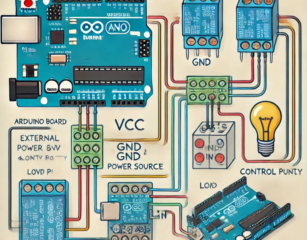
2️⃣ Schematic Diagram
Here’s how to wire these components:

Details of Connections:
- Relay Module: Connect the relay’s common (COM) pin to the external load, and the normally open (NO) pin to the external power source. The relay’s input (IN) is connected to the collector of the NPN transistor.
- Transistor: Acts as a switch controlled by the Arduino. Connect the emitter to the Arduino’s ground (GND), the collector to the relay input (IN), and the base through a resistor to a digital output pin on the Arduino (e.g., D2).
- Load: Connect one side to the external power source, and the other side to the normally open (NO) contact of the relay. When the relay is activated, it will close the circuit between the power source and the load.
Additional Components:
- Base Resistor: This resistor controls the amount of current going into the transistor’s base from the Arduino, preventing it from drawing too much current.
- Flyback Diode (optional in some cases): Placed across the relay coil (not shown in the schematic above), it protects the circuit from voltage spikes when the relay coil is de-energized.
3️⃣ Code Snippet for Arduino
To control the relay from the Arduino, you can use a simple sketch like this:
void setup() {
  pinMode(2, OUTPUT);  // Set D2 as an OUTPUT
}

void loop() {
  digitalWrite(2, HIGH);  // Turn on the relay
  delay(1000);            // Wait for one second
  digitalWrite(2, LOW);   // Turn off the relay
  delay(1000);            // Wait for one second
}
This code will toggle the relay on and off every second, switching the connected load accordingly.
4️⃣ Safety Tips
- Isolation: Ensure that the low-voltage (Arduino) and high-voltage sides of your circuit are well isolated to prevent electrical accidents.
- Verify Ratings: Always check that the relay’s voltage and current ratings match those of the load and power source.
This setup is ideal for controlling high-power devices safely and effectively using an Arduino and an external power source. Always exercise caution when working with electricity, especially at high voltages. If you have any further questions or need clarification on any part of the setup, feel free to ask!