A larger collector resistor gives a phototransistor a larger voltage change for the same light-induced current. It also leaves less room before the collector approaches ground. Put one Vishay TEPT4400 in a fixed light path and compare 47 kΩ with 4.7 kΩ. At each light setting, use the same measured drive current in the white LED. Then check where the two resistor readings can still describe the same detector current.
This experiment measures a steady response. The LED drive current is the repeatable control for the light source. The setup has no calibrated illuminance reference, and its results describe this LED, detector and spacing. The worksheet is blank. The program includes a constructed example to demonstrate the comparison.
Use the exact detector and emitter
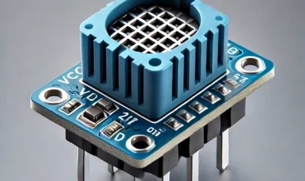
The Vishay TEPT4400 is a two-lead T-1 (3 mm) silicon phototransistor with N-type, P-type and N-type semiconductor regions. Light influences the current from collector C to emitter E. Connect C to the load resistor and E to ground. Identify the terminals from the view and dimensions on page 4 of Vishay document 81341, Rev. 1.8. Do this before trimming the leads. The diagram below labels both terminals. The device has no separate base terminal.
The detector’s collector-emitter absolute maximum is 6 V in that direction. Its reverse emitter-collector limit is 1.5 V. The 20 mA collector current and 100 mW power limits are absolute maxima under the listed temperature conditions. This fixture uses 5.00 V on the collector resistor and keeps the emitter at G0. Check polarity with the power off. Set the supply before connecting the detector and keep the measured rail from 4.90 to 5.10 V.
At 5 V collector-emitter bias Vishay lists 15–70 µA at 20 lx and about 200 µA typical at 100 lx. Those tests use the International Commission on Illumination (CIE) illuminant A, a standardized tungsten-like spectrum. The white LED here has a different spectrum. The device’s photo-current bins vary, and the LED’s current-to-light curve depends on its temperature. The manufacturer’s typical saturation voltage of 0.1 V uses its own 20 lx and 1.2 µA conditions. The lower-voltage flags used below are broader experiment screens.
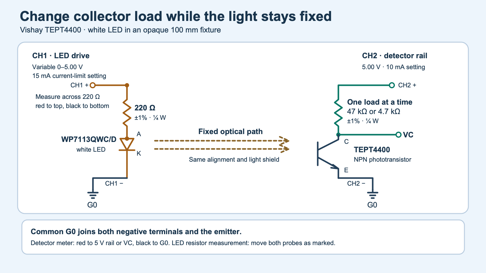
Use the Kingbright WP7113QWC/D 5 mm cool-white LED, a 220 Ω 1% ¼ W resistor, one 4.7 kΩ and one 47 kΩ 1% ¼ W resistor. The white LED’s current is set by a separate variable source and the 220 Ω series resistor. Kingbright’s exact V.6B data sheet gives 30 mA as the continuous absolute maximum at 25 °C. Keep the drive within the experiment’s 12 mA upper bound, with the supply’s current limit set to 15 mA. Verify the voltage across 220 Ω to determine LED current.
fixture.svg).Build two electrical branches and one optical path
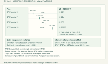
Use the two adjustable outputs of a SIGLENT SPD3303X in independent mode. With both outputs off, tie both negatives to G0 and leave the two positives separate. CH1 positive goes through 220 Ω to the LED anode, and the LED cathode returns to G0. CH2 positive goes through one collector load resistor to C. E returns to G0. The LED brightness control then has no direct electrical path to the detector’s collector resistor.
Hold the two lens tips facing each other along the axis of a matte-black tube, about 100 mm apart as a starting distance. Tape or clamp both positions before taking paired readings. Keep fingers and wire movement away from the optical path. Fit an opaque cover so room light cannot enter, and keep the LED pointed into the tube. A brighter or dimmer first trial is fine. Adjust the distance with power off during setup if the 47 kΩ output is already near ground at the lowest useful LED current or never approaches ground at the highest current. Once you begin recording, keep the chosen distance and geometry fixed for all rows.
With 5.10 V and the lowest 1% 4.7 kΩ value, 4.653 kΩ, the rail can deliver at most 1.10 mA through that load even if C is shorted to ground. For any collector voltage between the rails, transistor power in this load-line model is bounded by 5.10² ÷ (4 × 4653) W, about 1.40 mW. The 47 kΩ branch bounds are a tenth of those values. These are resistor-limited steady estimates.
Choose four matched illumination settings
- Use a Fluke 115 in its 6.000 V DC range with matching leads and fresh calibration. Start with CH1 off and CH2 at 5.00 V. With the 47 kΩ load fitted, measure the detector rail and C relative to G0. Move both floating meter probes to the two ends of the 220 Ω resistor, red toward CH1 positive. Record those three values for
dark_before,47k. Turn CH2 off, swap to 4.7 kΩ, restore CH2 and recorddark_before,4k7. - Find four LED current settings that rise clearly, for example approximately 0.5, 1.5, 4 and 8 mA. They correspond to about 0.110, 0.330, 0.880 and 1.760 V across 220 Ω. Start CH1 at 0 V and raise it slowly, keeping CH1 within 0–5 V and checking the actual drop. The LED forward voltage shifts the required CH1 setting. Wait for the drop and collector voltage to settle.
- Keep CH1 fixed for each pair. Power CH2 off to swap its load and restore it after the swap. Record the rail, collector and LED-resistor voltage first for 47 kΩ and then for 4.7 kΩ at every light setting. Move only the collector resistor and meter probes. The detector rail and LED current are checked independently in each row. Start the next pair after returning CH2 to the 47 kΩ arrangement with power off.
- After the fourth pair, turn CH1 off. Repeat the two dark readings and fill
dark_after. Recheck the cover if the collector sits appreciably below the detector rail in darkness. Repeat the entire trial if the dark control shifts or the paired LED currents differ. Keep any unresolved result with the setup notes.
Calculate current and check headroom
With detector rail VS, collector VC and known collector load RL, the resistor current is (VS − VC) / RL. The connected meter also draws some of that current. The Fluke 115 DC voltage input is greater than 10 MΩ, so the analyzer allows up to the upper collector-voltage bound divided by 10 MΩ for the meter branch. With the meter moved across 220 Ω, its parallel current also flows through the LED. The program uses the measured 220 Ω drop for the nominal drive and allows the additional meter current in its interval.
The program applies the meter’s ±(0.5% of reading + two 1 mV counts) to the entered voltages and ±1% to the three resistor values. The Fluke accuracy conditions include one year after calibration, 18–28 °C and 0–90% relative humidity. The derived current intervals include meter input current and can extend slightly below zero at a small voltage drop. Keep that uncertainty visible. The dark rows are checks for ambient leakage and repeatability.
At 5.00 V, a 47 kΩ load uses 85.1 µA of resistor current when the collector reaches 1.0 V. A 4.7 kΩ load needs 851 µA to reach that same voltage. The lower resistor thus leaves more collector voltage for a given current and gives a smaller voltage change. In a constructed example, 30 µA would give 3.59 V with 47 kΩ and about 4.86 V with 4.7 kΩ, neglecting meter current. At 120 µA the simple constant-current model would demand −0.64 V with 47 kΩ. This fixture cannot supply that voltage. The transistor then operates near the lower end of its load line and the resistor alone no longer measures an unrestricted current at the same light level.
When the entire collector voltage interval is at or below 0.50 V, the analyzer flags low headroom. When it is at or above 1.00 V, it classifies the node as clear of that low-end screen. The space between stays unresolved. The cutoffs are chosen for this fixture. Two headroom-clear currents with overlapping intervals are compatible at the applied LED drive. A 47 kΩ node that reaches low headroom while the 4.7 kΩ node remains clear shows that the larger resistor used up its voltage range first. A mismatch between two clear nodes can come from the detector’s dependence on collector voltage, movement or measurement differences. For a manually driven transistor circuit that uses the collector differently, see the 5 V 2N3904 LED switch experiment.
Run the full worksheet analyzer
Use the blank worksheet (ZIP: observations-blank.csv), with voltages in volts and one line per condition and resistor. Download collector_headroom.py (ZIP: collector_headroom.py) or the complete experiment ZIP (ZIP: experiment-tests-v1.zip). Run python3 collector_headroom.py observations-filled.csv. Exit 0 means the control rows and the drive comparison pass. It can still report unresolved headroom or disagreement in a specific light pair. Exit 3 preserves the measurements but withholds the light-pair interpretations when a control fails. Exit 2 reports invalid input. The synthetic worksheet (ZIP: synthetic-readings.csv) is for replaying the software.
The analyzer requires dark LED upper current at most 0.050 mA, a collector within 0.080 V of its rail, and dark repeat drops within 0.050 V. It uses overlapping paired LED-current intervals and a nominal difference no greater than 0.10 mA. Adjacent illumination intervals must be separated and the upper current must stay at or below 12 mA. These controls reduce differences in drive or room light. They do not measure the optical power at the detector.
"""Compare two TEPT4400 collector loads under matched LED drive."""
import argparse
import csv
import json
import math
from pathlib import Path
import sys

HEADER = ("step", "load", "detector_v", "collector_v", "led_resistor_v")
STEPS = ("dark_before", "light_1", "light_2", "light_3", "light_4", "dark_after")
LOADS = ("47k", "4k7")
EPS = 1e-9


def interval(volts):
    # Fluke 115, DC 6.000 V, 0.5% of reading plus 2 counts.
    error = abs(volts) * 0.005 + 0.002
    return volts - error, volts + error


def read_rows(path):
    if path.stat().st_size > 8192:
        raise ValueError("worksheet exceeds 8 KiB")
    with path.open(encoding="utf-8-sig", newline="") as stream:
        reader = csv.reader(stream, strict=True)
        if tuple(next(reader, ())) != HEADER:
            raise ValueError("use the exact worksheet headings")
        data = {}
        for step in STEPS:
            data[step] = {}
            for load in LOADS:
                row = next(reader, ())
                if len(row) != 5 or tuple(row[:2]) != (step, load):
                    raise ValueError(f"row {reader.line_num}: expected {step}, {load}")
                try:
                    supply, collector, led_resistor = map(float, row[2:])
                except ValueError:
                    raise ValueError(f"{step}, {load}: enter three volts readings") from None
                if not all(math.isfinite(v) for v in (supply, collector, led_resistor)):
                    raise ValueError(f"{step}, {load}: finite volts required")
                if not (4.90 <= supply <= 5.10 and -0.010 <= collector <= supply + 0.030
                        and -0.010 <= led_resistor <= 5.10):
                    raise ValueError(f"{step}, {load}: outside fixture voltage window")
                if any(abs(v * 1000 - round(v * 1000)) > 1e-6 for v in (supply, collector, led_resistor)):
                    raise ValueError(f"{step}, {load}: use 0.001 V meter display resolution")
                data[step][load] = supply, collector, led_resistor
        if next(reader, None) is not None:
            raise ValueError("unexpected extra row")
    return data


def current_from_drop(value, resistance, low, high):
    # The known resistance is a +/-1% part, not a calibrated measurement.
    nominal = value / resistance
    lower = low / (resistance * (1.01 if low >= 0 else 0.99))
    upper = high / (resistance * (0.99 if high >= 0 else 1.01))
    return nominal, [lower, upper]


def measure(values, load):
    supply, collector, led_resistor = values
    vl, vh = interval(supply)
    cl, ch = interval(collector)
    ll, lh = interval(led_resistor)
    feed, feed_span = current_from_drop(supply - collector, load, vl - ch, vh - cl)
    # The attached DC voltmeter is >10 Mohm; its draw is between 0 and VC/10 Mohm.
    feed_span[0] -= max(0, ch) / 10_000_000
    led, led_span = current_from_drop(led_resistor, 220, ll, lh)
    led_span[0] += min(0, ll) / 10_000_000
    led_span[1] += max(0, lh) / 10_000_000
    headroom = ("low_headroom" if ch <= 0.5 + EPS else
                "headroom_clear" if cl >= 1.0 - EPS else "headroom_uncertain")
    return dict(collector_v=collector, collector_interval_v=[cl, ch],
                resistor_current_ua=feed * 1e6, detector_current_interval_ua=[x * 1e6 for x in feed_span],
                led_current_ma=led * 1e3, led_current_interval_ma=[x * 1e3 for x in led_span],
                headroom=headroom)


def overlaps(first, second):
    return max(first[0], second[0]) <= min(first[1], second[1]) + EPS


def analyze(data):
    measured = {step: {load: measure(values, 47000 if load == "47k" else 4700)
                       for load, values in readings.items()} for step, readings in data.items()}
    dark = [measured[s][load] for s in (STEPS[0], STEPS[-1]) for load in LOADS]
    results = {}
    previous_drive_high = 0.050
    for step in STEPS[1:-1]:
        high, low = (measured[step][load] for load in LOADS)
        a, b = high["led_current_interval_ma"], low["led_current_interval_ma"]
        both_current_match = (overlaps(a, b) and abs(high["led_current_ma"] - low["led_current_ma"]) <= 0.10 + EPS)
        drive_clear = min(a[0], b[0]) > previous_drive_high + EPS and max(a[1], b[1]) <= 12 + EPS
        previous_drive_high = max(a[1], b[1])
        current_match = overlaps(high["detector_current_interval_ua"], low["detector_current_interval_ua"])
        if not both_current_match or not drive_clear:
            meaning = "illumination_control_unresolved"
        elif high["headroom"] == "low_headroom" and low["headroom"] == "headroom_clear":
            meaning = "47k_loses_collector_headroom"
        elif high["headroom"] == low["headroom"] == "headroom_clear":
            meaning = "compatible_current_intervals" if current_match else "current_intervals_disagree"
        else:
            meaning = "collector_headroom_unresolved"
        results[step] = dict(led_drive_matched=both_current_match, drive_step_clear=drive_clear,
                             current_intervals_overlap=current_match, interpretation=meaning)
    dark_checks = dict(
        led_off=all(row["led_current_interval_ma"][1] <= 0.050 + EPS for row in dark),
        collector_near_rail=all(abs(data[s][load][0] - data[s][load][1]) <= 0.080 + EPS
                                for s in (STEPS[0], STEPS[-1]) for load in LOADS),
        repeat_close=all(abs((data[STEPS[0]][load][0] - data[STEPS[0]][load][1]) -
                             (data[STEPS[-1]][load][0] - data[STEPS[-1]][load][1])) <= 0.050 + EPS
                         for load in LOADS),
    )
    controls = all(dark_checks.values()) and all(
        row["led_drive_matched"] and row["drive_step_clear"] for row in results.values())
    if not controls:
        for row in results.values():
            row["interpretation"] = "controls_unresolved"
    return dict(controls_pass=controls, dark_checks=dark_checks, measured=measured, comparison=results)


def main():
    parser = argparse.ArgumentParser(description=__doc__)
    parser.add_argument("worksheet", type=Path)
    args = parser.parse_args()
    try:
        result = analyze(read_rows(args.worksheet))
    except (OSError, ValueError, csv.Error) as error:
        print(f"worksheet rejected: {error}", file=sys.stderr)
        return 2
    print(json.dumps(result, indent=2, allow_nan=False))
    return 0 if result["controls_pass"] else 3


if __name__ == "__main__":
    sys.exit(main())
Challenge
Both loads are exposed to the same LED setting. The 47 kΩ collector interval is 0.23–0.27 V, while the 4.7 kΩ interval is 4.38–4.44 V. Which resistor still has collector voltage available, and can the first result calibrate illuminance?
The 4.7 kΩ node remains above the 1.00 V screen. The 47 kΩ node lies below the 0.50 V screen, so its resistor current describes the restricted load-line operating point. The LED current and the two collector voltages give no calibrated value in lux.
Manufacturer references
- Vishay TEPT4400 document 81341, including electrical characteristics and the terminal drawing, and the official product page.
- Kingbright exact WP7113QWC/D data sheet for polarity, package and electrical limits.
- SIGLENT SPD3303X documentation for independent isolated outputs.
- Fluke 115 user manual for DC input impedance and the 6.000 V range.
Download the complete reader files (ZIP) for the original editable drawing, PNG, worksheet and code in tept4400-collector-load-headroom. The full main program is also included above.