The reading changed. Did the light change?
Moving from a dark shelf to a bright desk is a useful light-sensor test. Changing the sensor’s range while leaving it on the same desk is a different test: can the program explain which exposure produced each number? A larger result after increasing gain is expected. An old result accidentally labelled with the new gain is a software error that can look equally convincing.
This experiment uses a TSL2591 carrier and an original Raspberry Pi Pico to collect four finite exposures: low gain for 100 milliseconds (ms), medium gain for 100 ms, medium gain for 200 ms, then low gain for 100 ms again. Gain is amplification before conversion; integration time is the interval during which the sensor accumulates light. Neither setting is a brightness unit. We retain both raw channels, reject clipped comparisons and demand evidence of a new conversion after each setting change.
The outcome is a range-switching experiment, not a calibrated lux meter. Lux describes illumination weighted approximately for human vision. Converting two detector channels into lux requires an appropriate optical model and calibration; those steps are deliberately outside this program. For the underlying ideas, try Light becomes a signal and Turn a voltage into a number.
Choose the carrier, not a guessed chip suffix
Use the Adafruit PID1980 TSL2591 STEMMA QT carrier, an original RP2040 Raspberry Pi Pico, four short jumper wires, soldered headers and a Universal Serial Bus (USB) cable. The software target is the official RPI_PICO MicroPython 1.26.0 build. A lamp with a steady setting, a fixed board support and an opaque card make the optical experiment repeatable. A digital multimeter, which measures voltage, is useful for the initial supply check.
There is an identity limit worth recording before the experiment. The current carrier schematic calls its sensor U1 “TSL2591”; the family’s identification register, a readable device-control byte, returns 0x50. Neither establishes the populated silicon’s full ordering suffix. The current ams OSRAM product page separately lists TSL25911FN, Q65114A0923. This lesson uses Adafruit’s supported PID1980 carrier interface; it does not declare that every shipped PID1980 contains that exact suffix. Record the purchased board revision and any traceable supplier documentation. Do not transfer these connections to an unverified bare chip or substitute the different input/output (I/O) voltage variant on the strength of a similar name.
For the manufacturer’s TSL25911FN reference, normal supply operation is 2.7–3.6 V; the 3.8 V absolute maximum is a damage boundary, not a target. Here the carrier input and Pico signals use 3.3 V. Adafruit explicitly supports powering this carrier from the controller’s 3.3 V supply. The carrier’s regulator introduces some drop, so check its 3Vo output against the supported operating range before collecting data. A reading on a multimeter does not check every transient.
Four wires and one shared supply
Disconnect USB before wiring. GND means ground, the common voltage reference. VIN is the carrier’s power input. The Inter-Integrated Circuit (I²C) bus uses serial clock (SCL) and serial data (SDA); these are shared digital lines with pull-up resistors, not analog detector outputs. An open-drain output either pulls its line LOW or releases it; the pull-up provides HIGH. The program uses I²C controller 0 at 100 kilohertz (kHz), or 100,000 clock cycles per second.
| Original Pico terminal | PID1980 header terminal | Purpose |
|---|---|---|
| 3V3_OUT, physical pin 36 | VIN, header pin 1 | Single 3.3 V power source |
| GND, physical pin 38 | GND, header pin 3 | Power return and logic reference |
| GP1, physical pin 2 | SCL, header pin 4 | I²C clock |
| GP0, physical pin 1 | SDA, header pin 5 | I²C data |
The wiring illustration has an editable Scalable Vector Graphics (SVG) original and a Portable Network Graphics (PNG) full-size image.
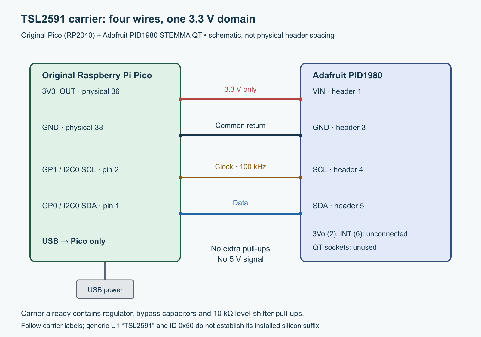
tricky-circuit-campaigns87-92/batch-009/images/pico-tsl2591-range-switching.svg) · Full-size PNG.Leave 3Vo, header pin 2, and the interrupt output INT, header pin 6, unconnected; the small STEMMA QT sockets are also unused. Do not connect carrier 3Vo back to Pico 3V3_OUT or add a second supply. Do not attach the Pico’s 5 V USB rail to either signal line. The pin numbers in the diagram identify electrical terminals; their drawn spacing is not a physical assembly guide.
The reviewed current carrier drawing includes an AP2112K-3.3 regulator, two 10 microfarad (µF) power capacitors, a 0.1 µF sensor bypass capacitor, and BSS138 level shifting with four 10 kilohm (kΩ) pull-ups. The capacitors support the local supply; pull-ups let the open-drain bus lines return HIGH. The controller-facing pull-ups go to VIN and the sensor-facing pair to the regulated rail. These parts are already on the carrier. Do not add another set of pull-ups for this short single-carrier trial. A nominal 3.3 V divided by 10 kΩ is 0.33 milliampere (mA) per pull-up; a conducting level shifter can involve both sides, so one resistor is not the complete bus-low current budget.
The seven-bit device address is 0x29. The family also responds at read-only address 0x28; seeing both during a scan does not establish two separate sensors. This program addresses only 0x29 and does not connect a second device at either occupied address.
Counts, gain and a ceiling that changes
Two analog-to-digital converters (ADCs) turn accumulated detector charge into integer counts. Channel 0 responds broadly to visible and infrared light, while channel 1 emphasizes infrared. Their difference is not automatically a calibrated visible-light measurement. Keep both channels in every record.
| Setting | Typical gain ratio, CH0 / CH1 | Interpretation |
|---|---|---|
| LOW | 1 / 1 | Starting reference range |
| MED | 24.5 / 24.5 | Actual specified ratios span 22–27 |
| HIGH | 400 / 400 | Actual specified ratios span 360–440 |
| MAX | 9200 / 9900 | Channel-dependent typical ratios |
The integration code 0 means nominal 100 ms; codes 1–5 mean 200–600 ms in 100 ms steps. At 100 ms the maximum count is 36863, rather than the full sixteen-bit range. At longer settings it is 65535. The program marks an exposure clipped if either channel reaches or exceeds its setting’s ceiling. The raw values remain available as evidence, but comparison values become None. A clipped value is not an illumination estimate that can be recovered by dividing it by gain.
For an unclipped record, the optional diagnostic scaling is:
comparison_ch0 = raw_ch0 / (typical_gain_ch0 × integration_steps)
comparison_ch1 = raw_ch1 / (typical_gain_ch1 × integration_steps)
integration_steps = atime_code + 1
This merely places numbers on an assumed LOW/100 ms count scale. For example, synthetic CH0 counts 1000, 24500 and 49000 at LOW/100, MED/100 and MED/200 all scale to 1000. Real results need not agree: gain variation, lamp flicker, optical movement and drift remain. MAX uses different divisors for the two channels. These values are not lux, and typical gains are not calibration coefficients.
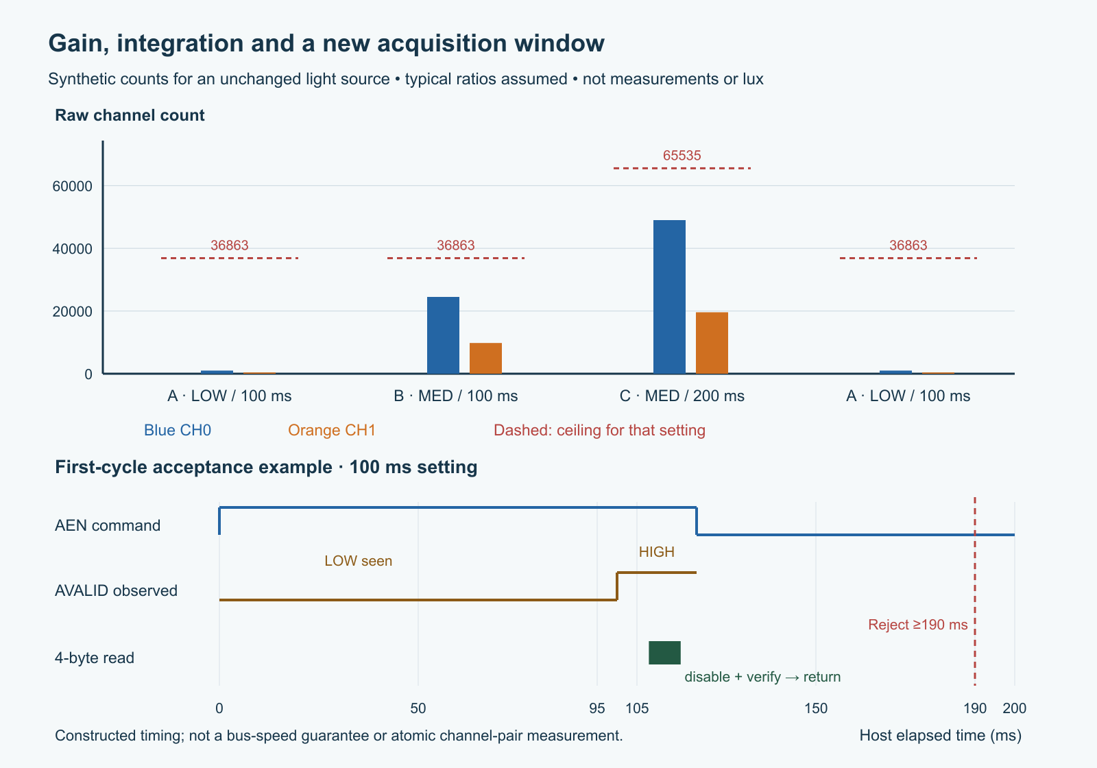
tricky-circuit-campaigns87-92/batch-009/images/pico-tsl2591-range-switching-logic.svg) · Full-size PNG.A valid bit is not a sample counter
The register named ENABLE contains the power-on oscillator control PON and ambient-light sensing enable AEN. We write 0 to disable them and 3 to enable both, leaving interrupts disabled. CONTROL holds gain in bits 5:4 and integration code in bits 2:0; reserved bits stay zero. Normal register commands use 0xA0 | register. STATUS bit 0, called AVALID, indicates that a conversion has completed since AEN was asserted. Reading a HIGH AVALID repeatedly does not prove that each read belongs to a new exposure.
Each acquisition therefore disables and verifies ENABLE, writes and verifies CONTROL, starts a new AEN epoch, and requires actually observing AVALID LOW before accepting HIGH. We do not assume that disabling AEN immediately clears that bit. If the first observation is already HIGH, the conservative result is an error, not a guessed timestamp.
For n = atime_code + 1, the datasheet’s integration step spans 95–105 ms. The code rejects HIGH earlier than 95 × n ms after the later host bound on the enable write, and stops waiting after 105 × n + 20 ms. Twenty milliseconds is our application margin, not a manufacturer guarantee. A fast valid conversion can be rejected because the host does not know the precise instant when AEN took effect; withholding an uncertain result is intentional.
The sensor starts another integration automatically. All data and surrounding configuration checks must therefore finish before 190 × n ms from the earlier host bound on enabling: twice the minimum integration time. A late I²C operation can miss that window and invalidate the run. The four data bytes are read sequentially from command 0xB4. Each channel’s low-byte read protects its own high-byte partner; the two channels have independent shadowing. Four sequential bytes reduce skew, but this is not an atomic channel-pair guarantee.
Host enable-before, enable-after and data-read-end timestamps describe program observations. They are neither exact integration start times nor timestamps from the detector. The first-cycle check relies on correct sensor operation, its specified timing, a continuously running host clock and exclusive bus ownership. An unnoticed reset, another program changing the sensor, or a long pause spanning a complete clock-counter wrap can defeat those assumptions. Do not use these records as synchronized scientific measurements.
The complete finite program
The driver has one sticky fault state: an uncertain bus acknowledgement, wrong identity, short read, register mismatch, missing invalid phase, early/late conversion or invalid host clock ends that session. An acknowledgement means the bus transaction was accepted; it does not establish a correct optical measurement. A BaseException handler also covers a keyboard interrupt. The failure path tries to disable the device and prevents reuse of the object. Correct the cause, stop the program and start a fresh session manually; the program does not silently restart after a sensor power interruption.
A successful exposure is returned only after a disable write and matching readback. If final cleanup cannot confirm disable, the overall run raises an error. Rows already printed cannot be withdrawn: retain the later session-invalid message with them. An acknowledged disable is still not physical proof that the carrier is unpowered. Its regulator and power indicator can remain on while conversion is disabled.
Download the complete Python program (ZIP; file: tricky-circuit-campaigns87-92/batch-009/code/pico-tsl2591-range-switching.py) · Blank observation worksheet (ZIP; file: tricky-circuit-campaigns87-92/batch-009/code/pico-tsl2591-range-switching-observations-blank.csv).
"""Pico / MicroPython 1.26.0, Adafruit PID1980 STEMMA QT carrier.
Raw, finite exposures; no lux calibration or physical-performance claim.
A fault invalidates this session. Restart manually after inspecting the cause.
"""

ADDR = 0x29
CMD = 0xA0
ENABLE, CONTROL, ID, STATUS, DATA = 0x00, 0x01, 0x12, 0x13, 0x14
GAIN_NAMES = ("LOW", "MED", "HIGH", "MAX")
# Datasheet typical ratios, not calibration constants. MAX differs by channel.
GAIN_TYP = ((1.0, 1.0), (24.5, 24.5), (400.0, 400.0), (9200.0, 9900.0))


class ExposureError(RuntimeError):
    pass


def setting(gain, atime):
    if type(gain) is not int or not 0 <= gain <= 3:
        raise ValueError("gain must be an integer 0..3")
    if type(atime) is not int or not 0 <= atime <= 5:
        raise ValueError("atime must be an integer 0..5")
    return (gain << 4) | atime


def describe(raw, gain, atime):
    """Keep clipped raw evidence, but withhold comparison values."""
    setting(gain, atime)
    if len(raw) != 4:
        raise ExposureError("SHORT_DATA")
    c0 = raw[0] | (raw[1] << 8)
    c1 = raw[2] | (raw[3] << 8)
    ceiling = 36863 if atime == 0 else 65535
    clipped = c0 >= ceiling or c1 >= ceiling
    ratios = GAIN_TYP[gain]
    scaled = None if clipped else (c0 / (ratios[0] * (atime + 1)),
                                   c1 / (ratios[1] * (atime + 1)))
    return {"ch0": c0, "ch1": c1, "ceiling": ceiling,
            "clipped": clipped, "comparison_counts": scaled,
            "comparison_is_calibrated": False}


class RawExposure:
    def __init__(self, bus, ticks_ms, ticks_diff, sleep_ms):
        # Constructor deliberately performs no I2C operation.
        self.bus, self.ticks, self.diff, self.sleep = bus, ticks_ms, ticks_diff, sleep_ms
        self.last_clock = None
        self.fault = None
        self.closed = False
        self.ready = False
        self.number = 0

    def _fail(self, reason):
        self.fault = self.fault or reason
        raise ExposureError(self.fault)

    def _now(self):
        try:
            now = self.ticks()
            if type(now) is not int:
                self._fail("CLOCK_TYPE")
            if self.last_clock is not None:
                gap = self.diff(now, self.last_clock)
                if type(gap) is not int or gap < 0 or gap > 2000:
                    self._fail("CLOCK_GAP")
            self.last_clock = now
            return now
        except BaseException:
            self.fault = self.fault or "CLOCK_FAULT"
            raise

    def _age(self, now, then):
        age = self.diff(now, then)
        if type(age) is not int or age < 0 or age > 2000:
            self._fail("CLOCK_AGE")
        return age

    def _read(self, register, count=1):
        data = self.bus.readfrom_mem(ADDR, CMD | register, count)
        if len(data) != count:
            self._fail("SHORT_READ")
        return data

    def _write(self, register, value):
        self.bus.writeto_mem(ADDR, CMD | register, bytes((value,)))

    def _expect(self, register, expected):
        if self._read(register)[0] != expected:
            self._fail("REGISTER_MISMATCH")

    def _off(self):
        self._write(ENABLE, 0)
        self._expect(ENABLE, 0)

    def begin(self):
        if self.closed or self.fault or self.ready:
            raise ExposureError("NEW_SESSION_REQUIRED")
        try:
            self._now()
            self._off()
            if self._read(ID)[0] != 0x50:
                self._fail("WRONG_ID")
            self.ready = True
        except BaseException:
            self.fault = self.fault or "BEGIN_FAULT"
            self.close()
            raise

    def exposure(self, gain, atime):
        config = setting(gain, atime)
        if not self.ready or self.closed or self.fault:
            raise ExposureError("NEW_SESSION_REQUIRED")
        steps = atime + 1
        try:
            self._now()
            self._off()
            self._write(CONTROL, config)
            self._expect(CONTROL, config)
            before_enable = self._now()
            self._write(ENABLE, 3)       # PON + AEN, interrupts remain disabled.
            self._expect(ENABLE, 3)
            after_enable = self._now()
            if self._age(after_enable, before_enable) >= 95 * steps:
                self._fail("ENABLE_WINDOW_LOST")
            # Do not assume the old AVALID bit clears just because AEN was LOW.
            first = self._read(STATUS)[0] & 1
            now = self._now()
            if first:
                self._fail("NO_OBSERVED_INVALID_PHASE")
            if self._age(now, before_enable) >= 95 * steps:
                self._fail("INVALID_PHASE_TOO_LATE")
            for _poll in range((105 * steps + 20) // 5 + 2):
                valid = self._read(STATUS)[0] & 1
                now = self._now()
                elapsed = self._age(now, before_enable)
                if elapsed > 105 * steps + 20:
                    self._fail("VALID_TIMEOUT")
                if valid:
                    # after_enable is the later host bound on the enable write.
                    if self._age(now, after_enable) < 95 * steps:
                        self._fail("EARLY_VALID")
                    break
                self.sleep(5)
            else:
                self._fail("POLL_BUDGET")
            self._expect(CONTROL, config)
            self._expect(ENABLE, 3)
            raw = self._read(DATA, 4)     # Per-channel shadow, not pair atomicity.
            data_read_end = self._now()
            self._expect(CONTROL, config)
            self._expect(ENABLE, 3)
            checked_end = self._now()
            if self._age(checked_end, before_enable) >= 190 * steps:
                self._fail("FIRST_CYCLE_WINDOW_LOST")
            # A sample is returned only after acknowledged disable + readback.
            self._off()
            self._now()
            result = describe(raw, gain, atime)
            self.number += 1
            result.update({"exposure": self.number, "gain": GAIN_NAMES[gain],
                           "atime_code": atime, "nominal_ms": 100 * steps,
                           "host_enable_before_ms": before_enable,
                           "host_enable_after_ms": after_enable,
                           "host_read_end_ms": data_read_end,
                           "host_read_elapsed_ms": self._age(data_read_end, before_enable),
                           "freshness": "observed_invalid_then_valid_first_window",
                           "pair_atomic": False})
            return result
        except BaseException:
            self.fault = self.fault or "EXPOSURE_FAULT"
            self.close()
            raise

    def close(self):
        """Best effort only: ACK/readback is not proof of physical power-off."""
        self.closed = True
        self.ready = False
        try:
            self._off()
            return True
        except BaseException:
            self.fault = self.fault or "DISABLE_UNCONFIRMED"
            return False


def run(bus, ticks_ms, ticks_diff, sleep_ms, emit=print):
    reader = RawExposure(bus, ticks_ms, ticks_diff, sleep_ms)
    try:
        reader.begin()
        emit("Raw TSL2591 exposures; comparison values are NOT lux.")
        # A/B/C/A: gain change, integration change, then starting range again.
        for gain, atime in ((0, 0), (1, 0), (1, 1), (0, 0)):
            result = reader.exposure(gain, atime)
            emit(result)
        return reader.number
    finally:
        if not reader.close():
            emit("INVALID SESSION: final disable was not confirmed")
            raise ExposureError("DISABLE_UNCONFIRMED")


def main():
    from machine import I2C, Pin
    from time import ticks_ms, ticks_diff, sleep_ms
    bus = I2C(0, sda=Pin(0), scl=Pin(1), freq=100000, timeout=50000)
    return run(bus, ticks_ms, ticks_diff, sleep_ms)


if __name__ == "__main__":
    main()
Copy the file to the Pico without naming it main.py, then use its read–evaluate–print loop (REPL), the interactive Python console, for one explicit run. The following command executes the complete file once; it is not a persistent startup installation.
with open("pico-tsl2591-range-switching.py") as source:
    program = source.read()
exec(program, {"__name__": "__main__"})
The pinned RP2 I²C implementation supports the selected 50,000-microsecond transaction timeout. A microsecond is one millionth of a second. Timeout support does not guarantee that every Python or bus operation meets the acceptance window. The driver also has a finite poll count, so a clock returning the same value forever cannot create an endless status loop. Tick differences handle an ordinary wrap; gaps above two seconds or backwards observations invalidate the session. A whole unobserved wrap cannot be detected from the counter alone.
Run a range trial you can explain
- Inspect with power removed. Confirm the carrier labels, four nets and no extra supply or pull-up board. Record the carrier revision and firmware version. Check that the light-sensitive surface is unobstructed.
- Power and check voltage. Plug USB into the Pico only. Measure carrier VIN and 3Vo against its GND. Investigate an out-of-range rail before continuing; do not probe the small sensor pins with a slipping meter tip.
- Fix the geometry. Place a stable lamp and the carrier on supports. Do not move either during the four-exposure trial. Keep hands out of the light path. Record lamp mode and nearby daylight.
- Run once and keep every row. Expect four exposure numbers, each with two raw counts, the selected range and host timing bounds. A clipped record is allowed diagnostic evidence, but its
comparison_countsmust beNone. An exception ends the run; do not splice later rows into it as if nothing happened. - Compare A/B/C/A. The final LOW/100 observation is a drift check against the first. If those change substantially, the middle comparisons cannot distinguish range effects from changing illumination. Try the same sequence again after stabilizing the setup.
- Explore clipping deliberately. With power off before moving wires, leave the electrical circuit unchanged. Change only light or the explicit exposure list. At stronger illumination, check whether either channel reaches its ceiling. Reduce gain or integration for a new exposure; never rescale the old clipped value into a supposed measurement.
- Check invalidation. Start a new session with the carrier disconnected while unpowered, then power the Pico and run: a bus error must produce no fabricated record. Reconnect only with power off. Timing and configuration fault cases are covered by the host checks described below; there is no need to short live bus lines.
Do not expect longer integration to eliminate all flicker. Lamp modulation, its phase relative to each exposure and optical drift can still alter counts. If repeatability matters, investigate those effects separately rather than treating agreement with the synthetic bars as a required result.
What has actually been checked
The delivered program has 28 host-executed test groups using fake bus and clock objects. They exercise every gain/time setting, both clipping channels and ceilings, little-endian byte assembly, stale and early valid flags, missing completion, delayed reads, changed registers, short replies, errors before and after write side effects, frozen/backwards/wrapped clocks, and console or keyboard-interrupt cleanup. Separate package checks compare the complete inline program, links, editable figures and blank worksheet. These are checks of the actual source’s decisions, not a sensor simulation validated against hardware.
No Pico firmware was built or run for this article, and no physical carrier, illumination accuracy, current consumption, bus waveform or optical repeatability was measured. The worksheet is intentionally empty. Before adopting the experiment in a logger, qualify the actual carrier identity, rail voltage, bus rise times and finite-window behavior on the exact assembled hardware.
Challenge: can a clipped value be rescued?
At MED/100 ms, CH0 returns 36863 and CH1 returns 12000. Dividing CH0 by the typical gain gives about 1504.6. Is that a usable LOW/100 estimate? What should the next exposure do?
Open the answer
No. CH0 has reached the 100 ms ceiling, so the amount by which the true integrated signal exceeded it is unknown. Keep both raw counts and the clipping flag, withhold both comparison values, then acquire again at lower gain. A fresh LOW/100 exposure is a reasonable next trial. Even an unclipped result is only a raw or typical-ratio comparison, not calibrated lux.
Primary references and limits
- ams OSRAM TSL25911 product and current ordering resources; TSL2591 DS000338 v3-00, 2023-Feb-08: supply limits, gain/integration tables, enable/status semantics and channel shadowing. The product download list and targeted manufacturer search did not surface a separate applicable errata document; that is not proof that none exists or that future revisions cannot change behavior. The TSL25913 discontinuation notice is not a blanket discontinuation of TSL25911.
- Adafruit PID1980, official carrier pinouts and editable carrier design: supported board-level supply and terminals. The reviewed schematic’s generic U1 label does not resolve installed silicon suffix.
- Original Pico R3 pinout: physical terminal numbers and I²C0 functions.
- MicroPython 1.26.0 I²C reference, tick-counter contract and pinned RP2 implementation: constructor arguments, memory-register transfers and timeout behavior.
Download the complete reader files (ZIP): full programs, blank observation worksheets, original editable SVG/PNG diagrams and selected support files for pico-tsl2591-range-switching. Inline main programs remain complete; this download is supplementary.