An optocoupler can pass a signal without a ground wire between two circuits. That does not mean it preserves every pulse. Build a low-voltage link with a Vishay VO617A-3, a battery-powered Pico sender and an Arduino UNO Rev3 receiver. First qualify the static current and logic levels, then compare sixteen commanded pulses with the low intervals actually observed by the UNO.
This is a locally reviewed design and host software experiment, not a built or measured prototype. Neither target program has been compiled or executed on its board here. The timing drawing is constructed. This breadboard exercise has no mains, installation-category or safety-isolation qualification.
What crosses the boundary
The optocoupler contains a light-emitting diode (LED) and a phototransistor, a transistor whose conduction is controlled by light. Current through the LED can make the transistor sink current in an electrically separate circuit. The input loop and output loop have different ground returns. Light carries the information; no signal wire or intentional ground wire crosses the gap.
The output is inverted: a high sender command lights the LED, tending to pull the receiver node low. That transition needs sufficient LED current, sufficient transistor current and enough time to cross the receiver’s logic threshold. A slow turn-off can lengthen the observed low interval. A weak or brief optical event may never become a recognizable low. Separately, software can miss an event that was electrically present. This experiment keeps those explanations distinct.
Exact parts and operating point
Use Vishay VO617A-3, the ordinary four-pin dual in-line package (DIP-4) with 7.62 mm row spacing. The suffix -3 selects a current-transfer-ratio bin; it is not the wider X006/X016 package or an unspecified PC817 module. Looking up the exact package matters because both terminal functions and isolation construction depend on the actual part.
The receiver is the classic Arduino UNO Rev3 with the ATmega328P-PU in its 28-pin plastic dual in-line package, running Arduino AVR Boards 1.8.6 at its normal 16 MHz. AVR names the controller architecture. The sender is an original RP2040 Raspberry Pi Pico running official MicroPython 1.26.0. Do not substitute a newer UNO variant and assume its input thresholds or interrupt mapping are identical. Programs are transferred over Universal Serial Bus (USB), which also carries a ground connection.
| Part | Value and job |
|---|---|
| U1 | Vishay VO617A-3, standard DIP-4; optical transfer |
| R1 | 1.00 kΩ, 1%, at least 0.125 W; limits input LED current |
| R2 | 100 kΩ, 1%; pulls the sender output node low while its pin is high impedance |
| R3 | 10 kΩ, 1%, at least 0.125 W; pulls the receiver collector to its own 5 V rail |
| Alternative R3 | 4.7 kΩ, 1%; a separate load trial, changed only without power |
| SW1 | Normally open pushbutton from Pico GP17 to sender ground |
| Sender supply | Three alkaline AAA cells in a holder; measured pack voltage within Pico’s 1.8–5.5 V VSYS range |
| Receiver supply | UNO USB connection only; no connection to sender power or ground |
V means volt, mA means milliampere, Ω means ohm, kΩ means a thousand ohms, W means watt, MHz means a million cycles per second, and ms and µs mean milliseconds and microseconds. USB ground can connect the two boards even when no signal jumper does. Unplug the Pico USB cable before claiming that the bench topology has separate ground domains.
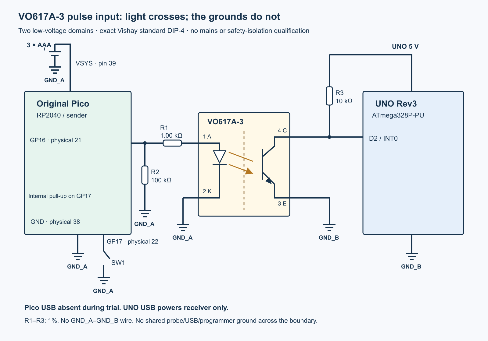
tricky-circuit-batch009-campaigns81-86/images/uno-opto-pulse-boundary.svg).Trace both current loops
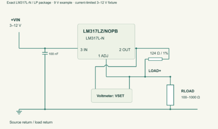
On the sender, connect Pico general-purpose input/output (GPIO) GP16, physical pin 21, to one end of R1. Connect R1’s other end to U1 pin 1, the LED anode. U1 pin 2, the cathode, returns to sender ground GND_A. R2 connects the GP16 end of R1 to GND_A. GP16 is the sole driver of this node; do not attach a second pulse generator to it. SW1 connects GP17, physical pin 22, to GND_A. The program enables GP17’s internal pull-up, which holds the unpressed button high.
The battery holder’s positive terminal connects to Pico VSYS physical pin 39; its negative terminal connects to Pico GND physical pin 38. Those grounds, the LED return, R2 and SW1 form domain A. Check battery polarity and voltage before connection. VSYS is the board’s system supply input, not the 3.3 V output and not VBUS pin 40. Use no second positive supply. The sender’s 3.3 V signal rail is generated by its board regulator; battery voltage is not applied directly to the LED pin.
On the receiver, U1 pin 4 is the phototransistor collector. Join it to UNO D2 and the lower end of R3. Connect R3’s upper end to the UNO 5 V pin. U1 pin 3, the emitter, connects to UNO GND. This is domain B. D2 maps to ATmega328P port PD2, physical pin 4, and external interrupt INT0. D2 is an input, never a competing output. The sketch disables the internal pull-up so the chosen external resistor defines the load.
Do not join GND_A and GND_B. A computer with both USB cables attached, a programmer, a common-ground bench supply or ordinary grounded oscilloscope probes on both domains can bypass that boundary. An isolated handheld meter can be used on one domain at a time after checking its own connections. Do not assume a multi-channel analyzer has independent grounds. A deliberately common-ground trial is a different topology, even if the optocoupler remains in its socket.
Current transfer is conditional
Current-transfer ratio (CTR) is collector current divided by LED forward current. For the -3 bin, Vishay specifies 100–200% at LED current 5 mA, collector-emitter voltage 5 V and ambient temperature 25 °C. Our direct GPIO fixture does not promise to reach that input current or maintain that collector voltage. Those bin limits cannot be reused as a guaranteed saturated-output current or switching speed.
R1 was chosen to keep this direct-drive experiment modest. With an assumed 3.3 V rail and the 1% low resistance of 990 Ω, even a zero-volt LED model would draw approximately 3.33 mA through R1. Add approximately 33 µA through the 1% low R2 value of 99 kΩ: the combined conditional output demand is about 3.37 mA. That is a conditional load calculation, not an absolute limit including supply tolerance or a short-circuit qualification. RP2040’s default 4 mA drive setting specifies a minimum high output of 2.62 V under its stated 3.3 V conditions; a pin is not an ideal 3.3 V source. The selected MicroPython RP2 port does not provide the generic drive keyword, so this code does not invent one.
Measure voltage VR1 across R1, not an assumed LED voltage:
IF = VR1 / actual R1
Example only: 2.00 V / 1000 Ω = 2.00 mA
Conditional load ceiling at assumed 3.3 V: 3.3 V / 990 Ω ≈ 3.33 mA
R2 demand at assumed 3.3 V: 3.3 V / 99 kΩ ≈ 33.3 µA
Combined conditional GPIO demand ≈ 3.367 mA
Conditional R1 power ceiling: 3.3² / 990 ≈ 11.0 mW

Receiver sink demand = (actual 5 V rail − actual VLOW) / actual R3
Assuming 5.0 V and VLOW = 0.4 V:
10 kΩ → 0.460 mA; 4.7 kΩ → 0.979 mA
mW means milliwatt. Measure VR1 with the meter directly across R1 during a static-on interval; the two meter leads are on the two ends of R1, rather than treating its voltage as a ground-referenced pin reading. Use the measured resistance for a better current estimate. The examples above are calculations, not measurements already made.
Vishay’s maximum 0.4 V collector-emitter saturation value is tested at 5 mA input and 1 mA collector current. We do not apply that guarantee to a measured 2 mA input. Saturation means that extra optical drive no longer produces a proportional collector-voltage change under the chosen load; stored charge can delay recovery. Lowering R3 increases demanded sink current and changes the turn-off behavior and the achievable low level. It can help one aspect and hurt another. Measure the result.
The quoted 60 mA LED current, 50 mA collector current and 80 V collector-emitter voltage are absolute maximum stresses, not targets for this project. The device’s isolation test voltage likewise is not a rating for these wires, breadboard spacing or instruments. The manufacturer’s switching figures are typical under specified test circuits, not a universal maximum pulse rate for this different load and current.
Qualify static levels before counting
Set STATIC_TEST=True in the sender file for a separate static trial. After the button sequence, it commands one ten-second on interval and then turns off. Use the off interval to measure the receiver high, and repeat finite static runs as needed to measure input current and output low. Record the temperature, resistor values and supply levels. Nothing in the receiver program automatically knows these measurements or verifies their validity.
For ordinary ATmega328P D2 input operation, the datasheet’s low-input maximum is 0.3 times VCC, the controller’s positive supply, and its high-input minimum is 0.6 times VCC. At an actually measured 5.0 V, that corresponds to low below 1.5 V and high above 3.0 V; values between are not qualified logic levels. Leave sensible margin rather than accepting a reading exactly on a boundary. Stop if the off and on states do not satisfy the limits under the actual conditions. Static success is necessary here, but does not qualify pulse edges.
A bounded pulse trial
After static qualification, set STATIC_TEST=False. Choose a requested high and low duration of 50,000, 5,000 or 500 µs in WIDTH_US. The sender issues sixteen high/low command pairs after a released button followed by a new stable press. Both button phases have a 30-second deadline with a 20 ms stability check. A held button at boot is not an immediate trigger. One run ends after one burst; a new trial requires a cold power cycle. The code attempts to command low in its cleanup path, but a failed pin write cannot prove that a physical output turned off.
The sender uses relative delays after each actual output call. Extra interpreter delay lengthens the command schedule; the code does not compress subsequent pulses to catch up with an absolute schedule. Requested durations and a commanded count are not measured optical pulse widths or proof that all sixteen electrical pulses occurred.
The receiver is armed by the single character g on its serial monitor. It first requires D2 high, then waits up to ten seconds for the first falling edge. Starting at that edge, it records a three-second receiver-time window. Sixteen 50 ms high/low commands take approximately 1.6 seconds before software overhead, leaving room inside that window. Press SW1 promptly after arming and within the sender’s own startup deadline. Do not send more serial characters while capturing.
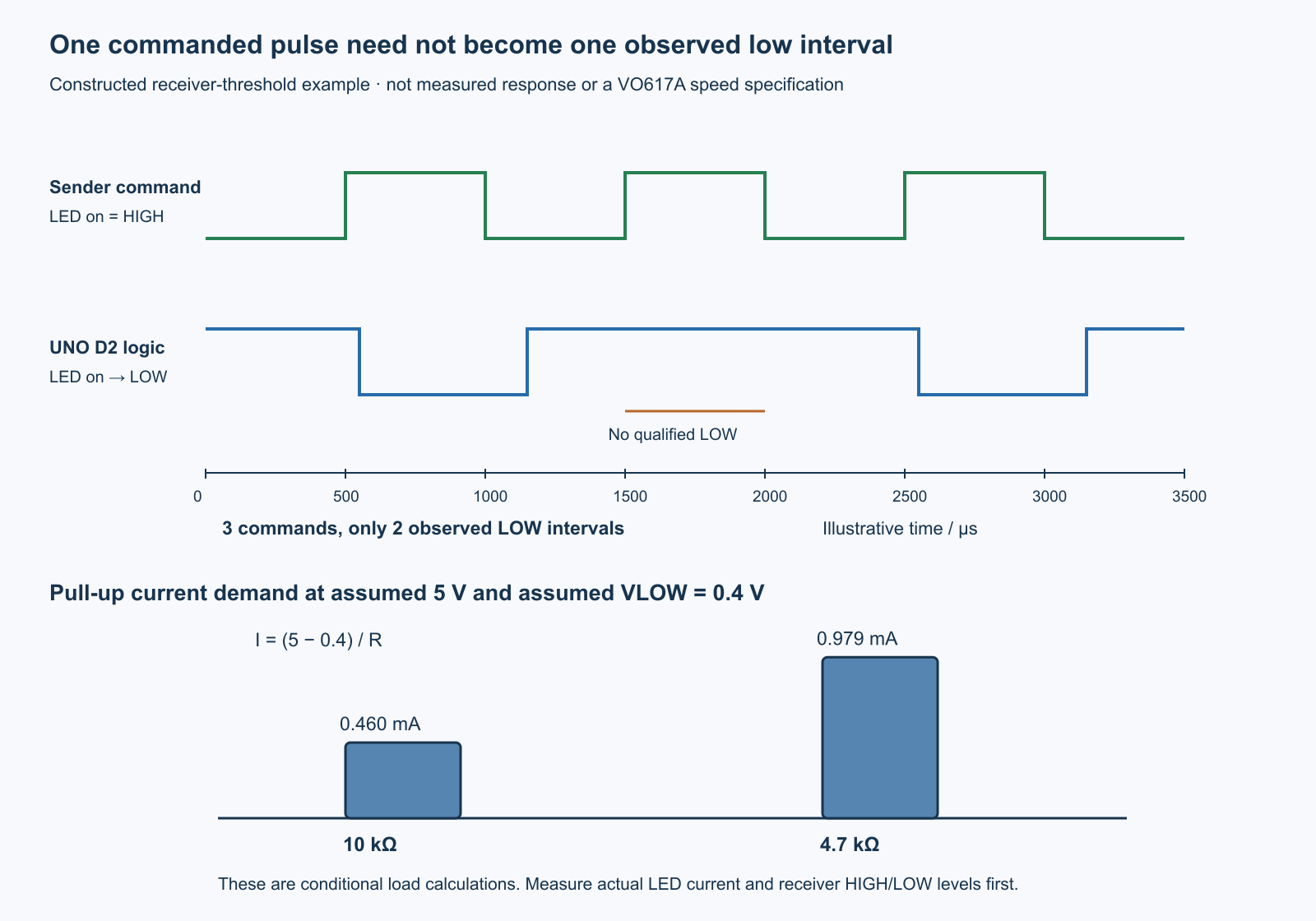
tricky-circuit-batch009-campaigns81-86/images/uno-opto-pulse-boundary-logic.svg).What the receiver accepts and rejects
An interrupt service routine (ISR) runs after an input change and records the current logic level and the local micros() time. This is software callback timing, not a hardware-captured optical-arrival timestamp. On the normal 16 MHz AVR core, the counter has nominal 4 µs granularity; interrupt latency, other interrupts, pin reading and clock error add uncertainty. The two boards’ clocks are independent, so never subtract their absolute timestamps.
The capture buffer has forty edge slots. Successful pairing needs exactly thirty-two alternating levels, starting low and ending high, for sixteen low intervals. An initial low, repeated observed level, zero/backward/ambiguous time difference, overflow, wrong count or a pending edge at the closing boundary rejects the result. Multi-byte timestamps are read atomically, meaning that an interrupt cannot change half a value while the main code reads the other half. The final copy occurs with the input interrupt masked; its pending hardware flag is checked before accepting the closed snapshot.
The result COUNT_OK means only that this receiver snapshot has the expected alternating edge count and internal consistency. It cannot prove one-to-one correspondence with physical sender events. Two lost transitions can leave the observed levels alternating; a missing pulse plus an extra glitch can even preserve the total count. A pending interrupt flag also is not an unlimited event queue. Once interrupts or the processor cannot keep up, no software test can reconstruct every absent edge from this record alone.
The program prints every observed edge and each accepted low width after capture, preserving evidence instead of silently inserting the commanded width. A mismatch is useful data, but not an automatic diagnosis of the optocoupler. Check static levels, electrical waveforms, loading, timing and receiver limitations separately. For more demanding rates, choose a properly specified interface and measurement method rather than declaring a maximum speed from this exercise.
Both full programs
Download the complete UNO C++ receiver (ZIP; file: tricky-circuit-batch009-campaigns81-86/code/uno-opto-pulse-boundary.cpp). A sketch is an Arduino program. Create a sketch folder with a matching empty .ino file and add this .cpp file unchanged; it already supplies setup() and loop(). Select classic UNO and Arduino AVR Boards 1.8.6, compile, inspect memory usage and upload. No actual AVR binary build or board execution has been performed here.
/* UNO Rev3 / Arduino AVR Boards1.8.6. No target build performed.
 * HOST_TEST compiles only the delivered edge/summary helpers.
 */
#include <stdint.h>
#define O86_MAX 40u
#define O86_EXPECTED 16u
#define O86_SEQUENCE 1u
#define O86_OVERFLOW 2u
#define O86_CLOCK 4u
#define O86_PENDING 8u
#define O86_IDLE_LOW 16u
struct O86Capture {
    uint32_t t[O86_MAX];
    uint8_t level[O86_MAX], used, fault;
};
struct O86Summary {
    uint32_t low_us[O86_EXPECTED], min_us, max_us;
    uint64_t sum_us;
    uint8_t pairs;
};
void o86_reset(volatile O86Capture *c) {
    c->used=0;c->fault=0;
    for(uint8_t i=0;i<O86_MAX;i++){c->t[i]=0;c->level[i]=1;}
}
void o86_record(volatile O86Capture *c,uint32_t now,uint8_t level) {
    if(c->fault)return;
    if(level>1u||level!=(c->used%2u)){c->fault|=O86_SEQUENCE;return;}
    if(c->used>=O86_MAX){c->fault|=O86_OVERFLOW;return;}
    if(c->used){uint32_t d=now-c->t[c->used-1];if(!d||d>=0x80000000UL){c->fault|=O86_CLOCK;return;}}
    uint8_t n=c->used;c->t[n]=now;c->level[n]=level;c->used=n+1;
}
bool o86_summary(const O86Capture *c,O86Summary *s) {
    s->pairs=0;s->sum_us=0;s->min_us=0xffffffffUL;s->max_us=0;
    if(c->fault||c->used!=2u*O86_EXPECTED)return false;
    for(uint8_t i=0;i<2u*O86_EXPECTED;i++){
        if(c->level[i]!=(i%2u))return false;
        if(i){uint32_t d=c->t[i]-c->t[i-1];if(!d||d>=0x80000000UL)return false;}
    }
    if((uint32_t)(c->t[c->used-1]-c->t[0])>=3000000UL)return false;
    for(uint8_t i=0;i<O86_EXPECTED;i++){
        uint32_t d=c->t[2*i+1]-c->t[2*i];s->low_us[i]=d;s->sum_us+=d;
        if(d<s->min_us)s->min_us=d;
        if(d>s->max_us)s->max_us=d;
        s->pairs++;
    }
    return true;
}
#ifndef HOST_TEST
#include <Arduino.h>
#include <util/atomic.h>
static volatile O86Capture captured;
static O86Capture frozen;
static O86Summary summary;
static void edge_irq(){o86_record(&captured,micros(),digitalRead(2)?1u:0u);}
static void close_capture(){
    ATOMIC_BLOCK(ATOMIC_RESTORESTATE){
        EIMSK&=(uint8_t)~_BV(INT0);
        if(EIFR&_BV(INTF0))captured.fault|=O86_PENDING;
        frozen.used=captured.used;frozen.fault=captured.fault;
        for(uint8_t i=0;i<O86_MAX;i++){frozen.t[i]=captured.t[i];frozen.level[i]=captured.level[i];}
    }
}
static void acquire(){
    Serial.println(F("ARM: press sender button now; send only one 16-pulse burst"));Serial.flush();
    ATOMIC_BLOCK(ATOMIC_RESTORESTATE){
        EIMSK&=(uint8_t)~_BV(INT0);o86_reset(&captured);EIFR=_BV(INTF0);
        if(!digitalRead(2))captured.fault|=O86_IDLE_LOW;
        else EIMSK|=_BV(INT0);
    }
    uint32_t armed=micros();bool seen=false;uint32_t first=0;
    while(true){
        uint8_t n,f;uint32_t t;
        ATOMIC_BLOCK(ATOMIC_RESTORESTATE){n=captured.used;f=captured.fault;t=captured.t[0];}
        if(f)break;
        if(n&&!seen){seen=true;first=t;}
        uint32_t now=micros();
        if(seen){if((uint32_t)(now-first)>=3000000UL)break;}
        else if((uint32_t)(now-armed)>=10000000UL)break;
    }
    close_capture();
    Serial.print(F("RAW edges="));Serial.print(frozen.used);Serial.print(F(" fault="));Serial.println(frozen.fault);
    for(uint8_t i=0;i<frozen.used;i++){
        Serial.print(i);Serial.print(',');Serial.print(frozen.t[i]);Serial.print(',');Serial.println(frozen.level[i]);
    }
    if(!o86_summary(&frozen,&summary)){Serial.println(F("INVALID: no complete qualified receiver burst; reset/rearm manually"));return;}
    Serial.println(F("COUNT_OK: receiver edges only, not a link-speed or timestamp-accuracy guarantee"));
    for(uint8_t i=0;i<summary.pairs;i++){Serial.print(F("LOW_US,"));Serial.print(i);Serial.print(',');Serial.println(summary.low_us[i]);}
    Serial.print(F("min_us="));Serial.print(summary.min_us);Serial.print(F(" max_us="));Serial.println(summary.max_us);
}
void setup(){
    Serial.begin(115200);pinMode(2,INPUT); // external pull-up, never INPUT_PULLUP
    attachInterrupt(digitalPinToInterrupt(2),edge_irq,CHANGE);
    EIMSK&=(uint8_t)~_BV(INT0);
    Serial.println(F("UNO opto receiver: type g once to arm; sender USB must be absent"));
}
void loop(){if(Serial.available()){char c=Serial.read();if(c=='g')acquire();}}
#endif
Download the complete Pico sender (ZIP; file: tricky-circuit-batch009-campaigns81-86/code/uno-opto-pulse-boundary-sender.py). With the battery and optocoupler wiring disconnected, use USB to save the selected configuration as main.py on the Pico. Remove USB before attaching the battery and beginning the isolated trial. This filename executes once at cold startup, then waits for the physical button. Do not attach a live USB interactive prompt for diagnostics across the supposed boundary.
"""Original Pico / MicroPython1.26.0. Battery VSYS; USB absent for optical trial.
Save as main.py only after unpowered wiring checks. One burst per cold boot.
"""
WIDTH_US=50000  # choose only50000,5000,500; change while USB-only, battery removed
COUNT=16
STATIC_TEST=False # True: one10s ON interval for manual DC current/level checks

def emit_burst(write,read_button,sleep_ms,sleep_us,ticks_ms,ticks_diff,width_us=WIDTH_US,static_test=False):
    def wait_button(level):
        start=ticks_ms()
        while True:
            age=ticks_diff(ticks_ms(),start)
            if type(age)is not int or age<0 or age>=30000:raise TimeoutError('button phase timeout')
            if read_button()==level:
                sleep_ms(20)
                age=ticks_diff(ticks_ms(),start)
                if type(age)is not int or age<0 or age>=30000:raise TimeoutError('button debounce deadline')
                if read_button()==level:return
            sleep_ms(1)
    try:
        write(0)
        if type(width_us)is not int or width_us not in(500,5000,50000):raise ValueError('unsupported width')
        if type(static_test)is not bool:raise ValueError('static_test must be bool')
        wait_button(1) # release required, held button at boot is not a trigger
        wait_button(0) # then a new press; no additional retrigger in this run
        if static_test:
            write(1);sleep_ms(10000);write(0)
        else:
            for _ in range(COUNT):
                write(1);sleep_us(width_us)
                write(0);sleep_us(width_us)
    finally:
        write(0) # one best-effort OFF attempt; failed GPIO write is not proof OFF
    if static_test:return {'commanded_static_on_ms':10000,'physical_current_measured':False}
    return {'commanded_pulses':COUNT,'requested_high_us':width_us,'requested_low_us':width_us}

def main():
    from machine import Pin
    from time import sleep_ms,sleep_us,ticks_ms,ticks_diff
    out=Pin(16,Pin.OUT,value=0)
    button=Pin(17,Pin.IN,Pin.PULL_UP)
    return emit_burst(out.value,button.value,sleep_ms,sleep_us,ticks_ms,ticks_diff,WIDTH_US,STATIC_TEST)

if __name__=='__main__':
    main()
Procedure and observations
- With both supplies removed, confirm U1’s exact marking and orientation. Trace pin 1/anode and pin 2/cathode only within domain A, and pin 4/collector and pin 3/emitter only within domain B. Check resistor values and verify there is no GND_A–GND_B wire.
- Compile and upload the UNO receiver. Prepare the Pico file separately with its battery removed and measurement wiring disconnected. Confirm
STATIC_TEST=Truefor the initial qualification. Remove the Pico USB cable before reconnecting its low-voltage wiring and battery. - Measure the battery and both local supply domains with suitable independent connections. During separate finite static runs, measure VR1 and actual receiver high/low levels. Treat these as operator observations, not a program-generated pass. Do not proceed when static logic margins are absent.
- Power down, select pulse mode and the slow 50,000 µs setting through the separate programming procedure, then restore the battery-only sender. On the UNO serial monitor at 115200 baud, send
gonce with no additional command traffic. After ARM, press SW1 promptly. Wait for the closed receiver report. - Record the configured sixteen-command pattern, actual observed edge count, raw receiver timestamps, status and low widths in the blank worksheet (ZIP; file:
tricky-circuit-batch009-campaigns81-86/code/uno-opto-pulse-boundary-observations-blank.csv). Keep commanded and observed fields separate. Do not replace missing observations with the expected number. - Repeat cold-start sessions at 5,000 µs and then 500 µs only after the slow test is understood. Keep current, wiring, pull-up and instruments unchanged within a comparison. If a trial fails, retain the invalid raw report and investigate; do not relabel it as a valid width measurement.
- For a separate load experiment, remove both supplies and replace R3 with 4.7 kΩ. Repeat static qualification before any pulse comparison. Record the changed sink demand and actual levels. A faster-looking release does not excuse an inadequate low level.
- For a fault observation, disconnect the sender-side LED path with all power off, then rearm a new run. A run with no observed edges should end in INVALID, with no invented events. A deliberately held-on static LED while arming should fail the initial-high requirement. These are proposed physical tests, not results already measured.
Use only properly isolated measurement connections if simultaneously observing both domains. For the simplest trial, take static readings with one independent meter at a time and use only the UNO-side log during the burst. If a scope ground or USB cable joins the domains, record that changed topology and stop describing that run as electrically separate. Never use this breadboard exercise to justify a hazardous-voltage connection.
Actual checks and remaining limits
Host tests compile the delivered C++ pairing and summary functions with a desktop compiler and execute the actual Python sender against injected pins, buttons and clocks. They cover selected widths, unsigned clock wrap, incomplete and lost pulses, duplicate edges, overflow, invalid snapshots, preserved nonuniform widths, held buttons, debounce deadlines, pin-write failures and interruptions. Independent fake-register checks can challenge the actual closing function. None measures phototransistor response or proves target interrupt timing.
The current Vishay product-linked sheet is document 83430, revision 2.8 dated 22 January 2025. Its product resources were checked for applicable updates; no separate applicable erratum was located there, which is not a claim that future changes cannot exist. Microchip’s separate normal-device errata DS80000855C (2024) was also checked. Its ATmega328/P summary covers a 32 kHz oscillator issue on revisions A/B, a two-wire interface (TWI) setup issue on revision D, and an analog-comparator multiplexer issue. This sketch uses none of those functions and does not change oscillator startup fuses. Record the actual silicon revision and recheck the relevant clarifications for a real build; this is not a blanket claim that the chip has no errata. The legacy ATmega328P product page marks it not recommended for new designs; this lesson uses an existing classic UNO rather than proposing a new production controller.
Challenge and answer
Challenge: You command sixteen pulses and observe fifteen well-formed low intervals. Can the receiver still calculate the fifteen widths and call the link qualified? Would replacing the 10 kΩ pull-up with 4.7 kΩ always fix the missing interval?
Show the answer
The raw intervals may help investigation, but this protocol rejects the burst because the expected count is missing. It must not present an accepted sixteen-pulse result. A lower pull-up asks the phototransistor to sink more current and changes recovery behavior. It might improve an edge or prevent the output from reaching a valid low. Recheck actual input current and static levels, then measure the particular circuit. Optical isolation and correct pulse transfer are separate properties.
For the foundations, review the diode lesson, and the electronics course. The core lesson here is the boundary between an electrical transfer mechanism and the evidence that a particular pulse was observed.
Primary sources
- Vishay VO617A datasheet, document 83430, revision 2.8, 22 January 2025: package pinout, ordering, current-transfer bin, stress limits, saturation and switching test conditions.
- Vishay VO617A product resources.
- Arduino UNO Rev3 hardware documentation and official through-hole board schematic.
- Microchip ATmega328/P full datasheet DS40002061B and the exact device’s current document listing.
- Microchip normal-device silicon errata DS80000855C, 2024; device/revision applicability and clarifications.
- Arduino AVR core 1.8.6 interrupt implementation, standard pin mapping, and microsecond timing implementation.
- Original Pico R3 pinout, Pico power architecture, and RP2040 digital output characteristics, Table 625.
- MicroPython 1.26.0 Pin reference and the pinned RP2 implementation.
Download the reader files (ZIP): complete source code, the blank observation worksheet and original editable SVG/PNG diagrams for uno-opto-pulse-boundary are inside tricky-circuit-batch009-campaigns81-86/. All inline programs are complete; the download is supplementary.